
Automatic assembling system and assembling method for combined cam shaft

An automatic assembly and camshaft technology, which is applied in the direction of measuring devices, instruments, torque measurement, etc., can solve the problems of cumbersome torque detection operation, inability to detect torque, inability to combine camshaft positioning torque detection, etc.

Active Publication Date: 2017-01-04
MIANYANG BRILLIANCE RUIAN AUTOMOTIVE COMPONENTS
View PDF5 Cites 6 Cited by
  • Summary
  • Abstract
  • Description
  • Claims
  • Application Information

AI Technical Summary

Problems solved by technology

The existing technology cannot realize the torque detection of the steel pipe and the torque detection between the steel pipe and the cam through a torque detection mechanism. The traditional torque detection mechanism often has a complicated structure when detecting the combined camshaft, and the torque detection operation is also difficult. It is cumbersome, and it is impossible to realize the fast positioning torque detection of each position of the combined camshaft, and the traditional torque detection mechanism cannot perform torque detection on the torque applied to the combined camshaft

Method used


Image

  • Automatic assembling system and assembling method for combined cam shaft
  • Automatic assembling system and assembling method for combined cam shaft
  • Automatic assembling system and assembling method for combined cam shaft

Examples


Embodiment

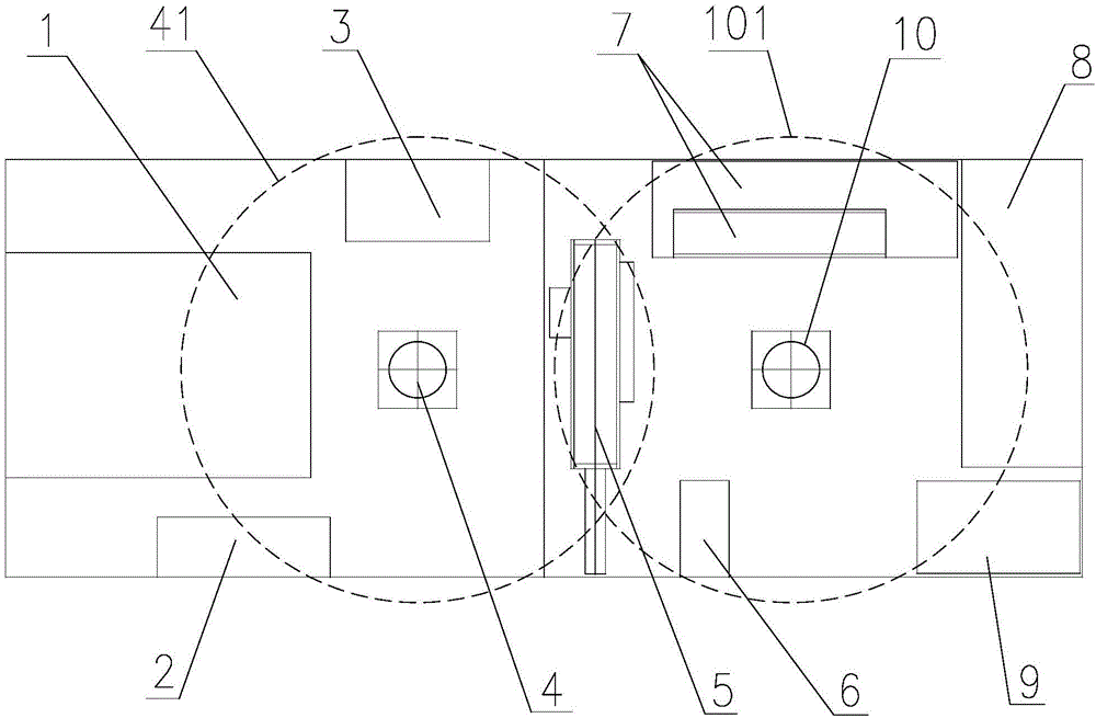
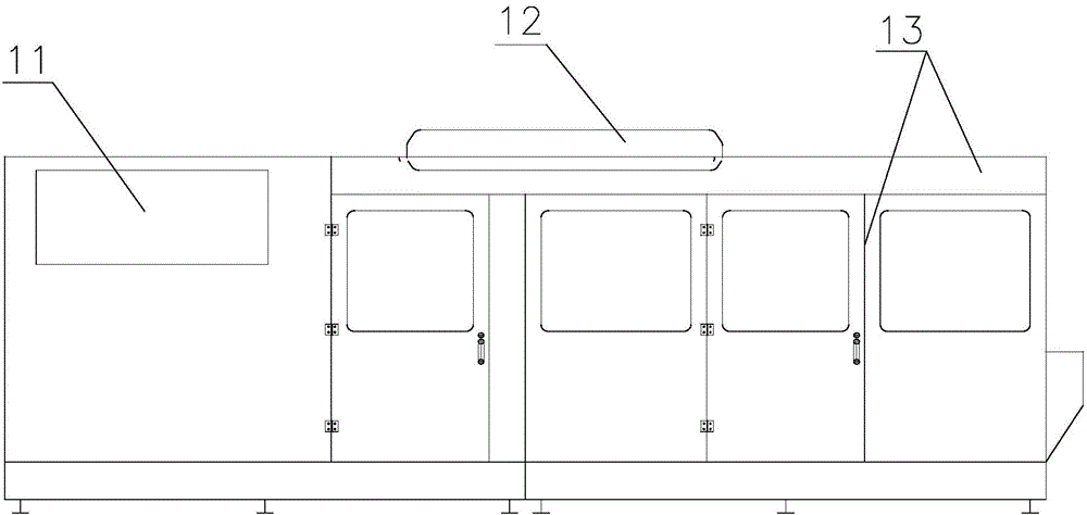
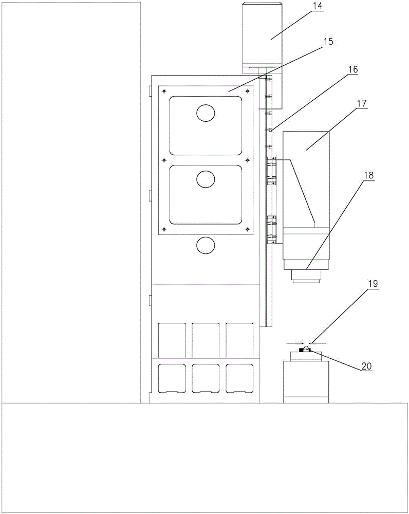
[0048] like Figure 1 to Figure 5 As shown, a combined camshaft automatic assembly system includes a first robot 4 and a second robot 10, and the area around the first robot 4 is equipped with an assembly machine 1, a steel pipe silo 2, an assembly parts silo 3, and a steel pipe silo 2 is used to hold the steel pipe 541 required for the assembly of the combined camshaft, the assembly parts bin 3 is used to hold the cam 542 required for the assembly of the combined camshaft, and the assembly machine 1 is used to install several cams on the outside of the steel pipe to assemble the combined cam Shaft initial product; the area around the second robot 10 is equipped with a stretching machine 5, a laser code scanning device 6, an end assembly assembly device 7, a torque detection device 8, and a finished product storage and transportation device 9, and the stretching machine 5 is used In the steel pipe 541 of the original product of the combined camshaft, the steel ball 541 and the...


PUM


Abstract

The invention discloses an automatic assembling system and an automatic assembling method for a combined cam shaft. The automatic assembling system for the combined cam shaft comprises a first robot and a second robot; an assembling machine, a steel tube cabin and an assembling part cabin are arranged on the peripheral region of the first robot in a matched manner; a swelling machine, a laser coding and code scanning device, an end part assembling part assembling device, a twisting force detecting device and a finished product storage transportation device are arranged on the peripheral region of the second robot in a matched manner; the swelling machine, the end part assembling part assembling device and the twisting force detecting device are respectively in electric communication connection with the laser coding and code scanning device. According to the automatic assembling system and the automatic assembling method for the combined cam shaft, the swelling force during a production process of the combined cam shaft, the end part assembling part mounting pressure and the torque force in torque detecting can be detected in real time, and the detected data are stored in coding codes corresponding to the combined cam shaft, so that the subsequent quality of the combined cam shaft is beneficially tracked, fault problems are beneficially eliminated and the machining quality is beneficially improved.

Description

technical field [0001] The invention relates to the technical field of assembling and assembling combined camshafts, in particular to an automatic assembling system and an assembling method for combined camshafts. Background technique [0002] Combination camshafts include steel pipes and cams arranged outside the steel pipes. End fittings need to be installed at the nozzles at both ends of the steel pipes. When producing and processing composite camshafts with traditional technology, each processing station is often separated and adjacent to each other. The parts are conveyed between the two processing stations through the conveyor belt, which will take up a large processing space. In addition, the tension force during the production process of the combined camshaft, the installation pressure of the end assembly, and the torque force during the torque detection cannot be detected and stored in real time, so that various indicators during the production process of the combin...

Claims


Application Information

Patent Timeline
IPC IPC(8): B23P19/027G01L3/02
CPCB23P19/027G01L3/02
Inventor 秦祖安舒万强蔡勇李聪明王莲瞿贵峰
Owner MIANYANG BRILLIANCE RUIAN AUTOMOTIVE COMPONENTS
Learn More