Part angle alignment method and clamp thereof

A technology of parts and angles, which is applied in the field of aligning tooling for machining, can solve problems such as high skill level requirements for operators, incorrect input of angle parameters, and complicated operation procedures, so that it is not easy to operate incorrectly and align Accurate, simple operation effect

Active Publication Date: 2017-01-04
AECC AVIATION POWER CO LTD
View PDF8 Cites 17 Cited by
  • Summary
  • Abstract
  • Description
  • Claims
  • Application Information

AI Technical Summary

Problems solved by technology

[0004] For the machining of parts with holes or hole groups with mutual angular relationship on the CNC machine tool, in the early stage of part alignment, especially when setting the 0 degree position of the machining origin, the current commonly used method is to directly align the parts Calculate the angle between the hole and the 0-degree position, and then determine the final 0-degree position by inputting the angular value in the parameter of the machine origin setting command; for parts that cannot be directly aligned For parts with offset holes, auxiliary tools are generally used when setting the angle, such as positioning pins, measuring rods, etc. When using, insert the positioning pins into the existing angular alignment holes on the part, and then use the micrometer The head of the table is used to find the position of the positioning pin to get the position of the angular alignment hole of the part, and then calculate the angular size between the hole and the 0 degree position, and then input the angular direction in the parameters of the machine tool origin setting command. However, in the actual operation process, due to the complexity of the above-mentioned operation process, the operator's skill level is relatively high, and it is prone to inaccurate alignment, conversion errors, and angular parameter input errors, etc. The occurrence of the situation will eventually lead to the scrapping of parts, causing unnecessary economic losses

Method used


Image

  • Part angle alignment method and clamp thereof
  • Part angle alignment method and clamp thereof
  • Part angle alignment method and clamp thereof

Examples


Embodiment Construction

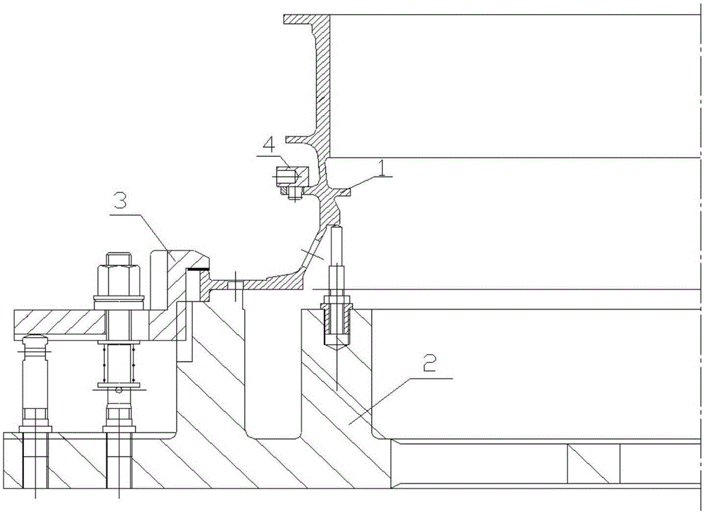
[0030] In the description of the present invention, it should be understood that the orientation or positional relationship indicated by the terms "radial", "upper", "outer", "vertical" etc. is based on the orientation or positional relationship shown in the accompanying drawings, only It is for the convenience of describing the present invention and simplifying the description, but does not indicate or imply that the referred device or element must have a specific orientation, be constructed and operated in a specific orientation, and thus should not be construed as limiting the present invention. In the description of the present invention, unless otherwise specified, "plurality" means two or more.

[0031] In the description of the present invention, it should be noted that, unless otherwise clearly specified and limited, the terms "arrangement", "connection" and "connection" should be understood in a broad sense, for example, it can be a fixed connection or a detachable con...


PUM


Abstract

The invention discloses a part angle alignment method and a clamp thereof. The method comprises the steps that a process alignment block is firstly manufactured according to the structure of a part, a process alignment hole and mounting holes are machined in the process alignment block, and the process alignment hole or an angular straightening face is machined at the zero-degree position of the clamp; then the clamp is mounted on a machine tool, the process alignment hole or the angular straightening face on the clamp is aligned, the zero-degree angular position is set, and the clamp is pressed; the part is mounted on the clamp and pressed; then the process alignment block is mounted on the part through the process alignment hole and the mounting holes in the process alignment block; finally, a dial indicator is used for metering to straighten the angular straightening face on the clamp and align the alignment hole in the clamp to determine the zero-degree position, the process hole in the part or the process alignment hole in the process alignment block is aligned, the zero-degree angular position of the part is determined, and the zero-degree position of the machine tool is determined. The method is simple in operation process, reasonable in step and accurate in alignment, and by directly aligning an angular alignment locating hole in a locating block, the method is convenient to use and suitable for machining of batched parts.

Description

[0001] 【Technical field】 [0002] The invention belongs to the technical field of aligning tooling for mechanical processing, and in particular relates to a method for aligning the angular direction of parts and a fixture thereof. [0003] 【Background technique】 [0004] For the machining of parts with holes or hole groups with mutual angular relationship on the CNC machine tool, in the early stage of part alignment, especially when setting the 0 degree position of the machining origin, the current commonly used method is to directly align the parts Calculate the angle between the hole and the 0-degree position, and then determine the final 0-degree position by inputting the angular value in the parameter of the machine origin setting command; for parts that cannot be directly aligned For parts with offset holes, auxiliary tools are generally used when setting the angle, such as positioning pins, measuring rods, etc. When using, insert the positioning pins into the existing ang...

Claims


Application Information

Patent Timeline
Patent Type & Authority Applications(China)
IPC IPC(8): B23Q3/18B23Q3/06
CPCB23Q3/06B23Q3/18
Inventor 王元祥艾明明任景刚唐小平王楠轶田浩池
Owner AECC AVIATION POWER CO LTD
Why Eureka
Try Eureka