
Die cutting machine with efficient die cutting tool

A die-cutting machine and die-cutting technology, applied in metal processing and other directions, can solve problems such as reducing production failure rate, and achieve the effect of solving paper adsorption, simple structure and improving die-cutting efficiency.

Active Publication Date: 2017-01-04
天津市文雅印刷标识有限公司
View PDF10 Cites 6 Cited by
  • Summary
  • Abstract
  • Description
  • Claims
  • Application Information

AI Technical Summary

Problems solved by technology

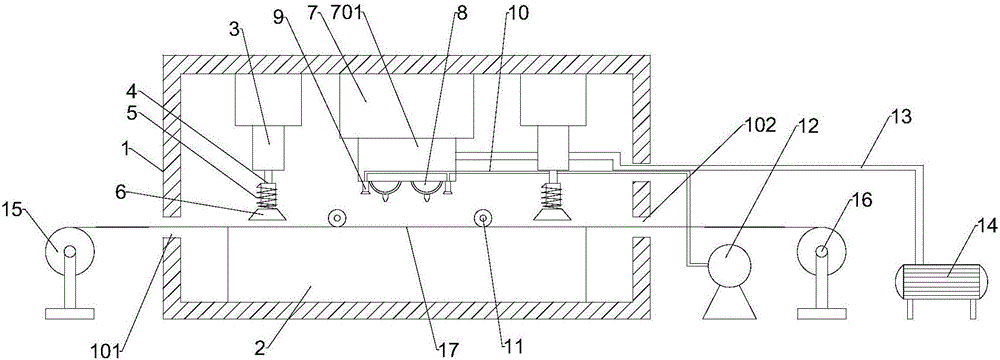
[0003] In view of this, the present invention aims to propose a die-cutting machine with a high-efficiency die-cutting tool to ensure that the paper moves forward smoothly after being die-cut, which effectively solves the problem of the paper absorbing the tool and reduces the production failure rate

Method used


Image

  • Die cutting machine with efficient die cutting tool
  • Die cutting machine with efficient die cutting tool

Examples


Embodiment Construction

[0022] It should be noted that the embodiments in the invention and the features in the embodiments can be combined with each other if there is no conflict.

[0023] In the description of the invention, it should be understood that the terms "center", "vertical", "horizontal", "upper", "lower", "front", "rear", "left", "right", The orientation or positional relationship indicated by "vertical", "horizontal", "top", "bottom", "inner", "outer", etc. is based on the orientation or positional relationship shown in the drawings, and is only for the convenience of describing the present invention The creation and simplification of the description does not indicate or imply that the pointed device or element must have a specific orientation, be constructed and operated in a specific orientation, and therefore cannot be understood as a limitation of the invention. In addition, the terms "first", "second", etc. are only used for descriptive purposes, and cannot be understood as indicating...


PUM


Abstract

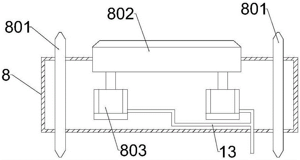
The invention provides a die cutting machine with an efficient die cutting tool. A connecting base is fixedly connected with a plurality of downward air blowing nozzles which sequentially communicate through an air inlet pipe. The other end of the air inlet pipe is connected with an air supply machine. The two sides of the part, in a machine case, of the connecting base are provided with downward pressing air cylinders correspondingly. The end portions of piston rods of the downward pressing air cylinders are fixedly connected with connecting rods sleeved with elastic pieces. One end of each elastic piece is fixedly connected with the corresponding connecting rod, and the other end of each elastic piece is connected with a pressing block. The pressing blocks face paper, and the pressing blocks can move relative to the connecting rods under the action force of the elastic pieces. The novel die cutting machine is simple in structure, transverse die cutting and longitudinal die cutting can be conducted on the paper at the same time, two tool rollers are arranged and can cut two printed products at the same time, the die cutting efficiency is improved, and the problem of paper adsorption in the die cutting process is effectively solved as well.

Description

Technical field [0001] The invention belongs to the technical field of printing production equipment, and particularly relates to a die-cutting machine with a high-efficiency die-cutting tool. Background technique [0002] After the paper is printed, the paper enters the die-cutting station. Through the extrusion of the upper and lower die-cutting plates, the knife board on the die-cutting board divides the paper into the required size. In the actual production process, the horizontal and vertical die-cutting Two processes are required, which cannot be carried out at the same time. When the die-cutting board completes one die-cutting and the upper die-cutting board moves upward, due to static electricity or the vacuum suction effect generated at the moment when the two die-cutting boards separate, the paper that is die-cut is often It is adsorbed on the knife board of the upper die-cutting board, which causes paper jam failure. Therefore, a device that can effectively solve the p...

Claims


Application Information

Patent Timeline
Patent Type & Authority Applications(China)
IPC IPC(8): B26F1/38B26F1/44B26D5/04B26D7/02B26D7/27
CPCB26D5/04B26D7/015B26D7/025B26D7/27B26F1/384B26F1/44
Inventor 王国良
Owner 天津市文雅印刷标识有限公司
Learn More