
Waste shoe mold quick smashing device for shoe industry
A crushing device and shoe mold technology, applied in recycling technology, grain processing, mechanical material recycling, etc., can solve the problems of complex operation, low work efficiency, poor crushing effect, etc., and achieve small size of the device, high work efficiency, The effect of novel structure
- Summary
- Abstract
- Description
- Claims
- Application Information
AI Technical Summary
Problems solved by technology
Method used
Image

Examples
Embodiment 1
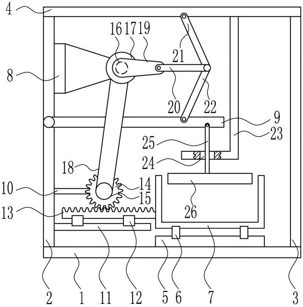
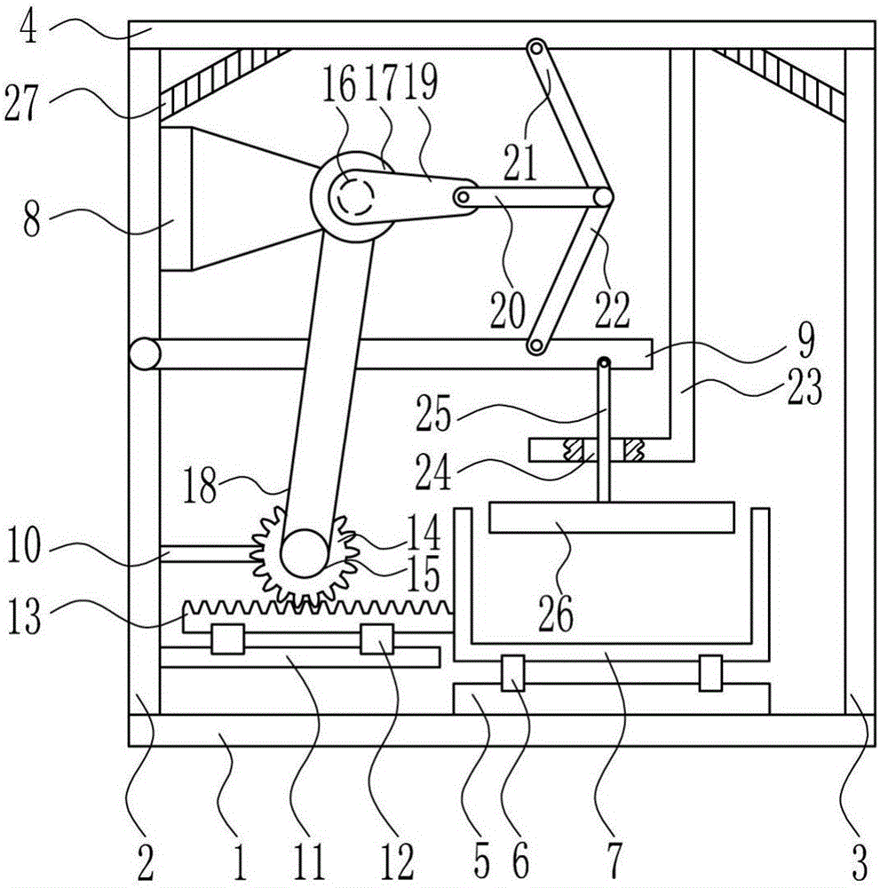
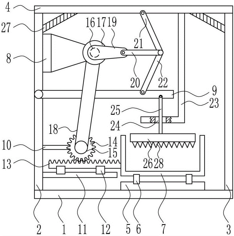
[0030] A quick crushing device for waste shoe molds used in the shoe industry, such as Figure 1-4 As shown, it includes bottom plate 1, left frame 2, right frame 3, top plate 4, first slide rail 5, first slide block 6, crushing frame 7, mounting seat 8, swing rod 9, support rod 10, second slide Rail 11, second slider 12, rack 13, gear 14, small pulley 15, motor 16, large pulley 17, flat belt 18, crank 19, first connecting rod 20, second connecting rod 21, third connecting rod 22. Guide plate 23, lifting rod 25 and breaker 26. The top of bottom plate 1 is provided with left frame 2, first slide rail 5 and right frame 3 in sequence from left to right, and top plate 4 is provided at the top of left frame 2 and right frame 3. , the first slide rail 5 is slidably connected with a first slider 6, the first slider 6 is provided with a crushing frame 7, the upper part of the left frame 2 right side is provided with a mounting seat 8, and a motor 16 is installed on the mounting seat 8...
PUM
 Abstract
Description
Claims
Application Information