Plastic forming die for cylinder and irregular three-head spiral groove on side surface thereof

A plastic forming and spiral groove technology, applied in the field of cylindrical and spiral groove forming molds, can solve the problems of workpiece burrs, poor quality, and many processes, and achieve the effects of accurate size, convenient operation and improved work efficiency.

Active Publication Date: 2017-01-04
中壹发展八五零电子有限公司
View PDF1 Cites 1 Cited by
  • Summary
  • Abstract
  • Description
  • Claims
  • Application Information

AI Technical Summary

Problems solved by technology

[0003] The purpose of the present invention is to provide a plastic molding mold with a cylinder and irregular three-headed spiral grooves on its side to solve the problems of serious burrs, many processes, low efficiency, and poor quality of workpieces produced by existing molds.

Method used


Image

  • Plastic forming die for cylinder and irregular three-head spiral groove on side surface thereof
  • Plastic forming die for cylinder and irregular three-head spiral groove on side surface thereof
  • Plastic forming die for cylinder and irregular three-head spiral groove on side surface thereof

Examples


Embodiment Construction

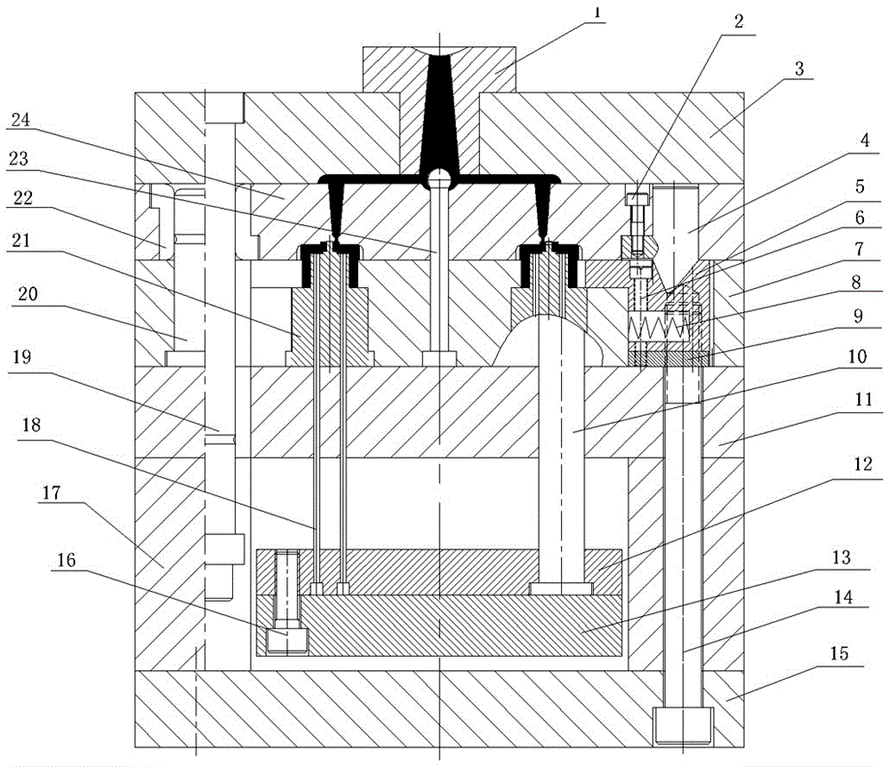
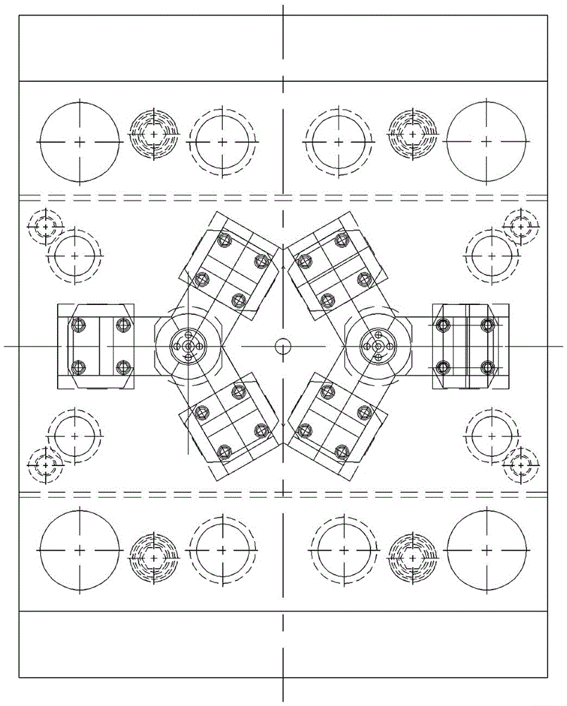
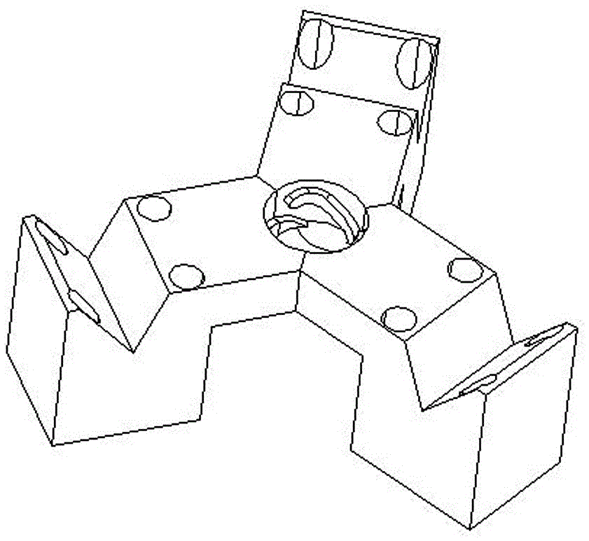
[0023] Such as Figure 1~5 As shown, the present invention mainly comprises fixed mold and movable mold, and wherein, fixed mold comprises upper mold base 3 and fixed cavity plate 24; mechanism.

[0024] In the fixed mould, the upper mold base 3 is connected with the molding equipment, the fixed cavity plate 24 is arranged in parallel with the upper mold base 3, and the two are connected through the drawing plate guide post 19, so that after the injection molding is completed, the drawing plate guide post 19 makes the The upper mold base 3 is separated from the fixed cavity plate 24 . The cavity-fixing plate 24 is provided with an oblique guide post 4, runners and two vertically symmetrical molding cavities, the lower end of the oblique guide post 4 is V-shaped, and it is fixedly connected to the cavity-fixing plate 24 via the first screw 2. . The inclined guide post 4 moves and presses the slide block 5 to ensure the accuracy of the shape and size of the formed workpiece. ...


PUM


Abstract

The invention provides a plastic forming die for a cylinder and an irregular three-head spiral groove in the side surface thereof. The plastic forming die comprises a fixed die and a moving die in folding with the fixed die; the fixed die comprises an upper die seat and a fixed cavity plate, the upper die seat is connected with molding equipment, and the upper die seat is parallel to the fixed cavity plate and connected with the fixed cavity plate through a pull plate guide post; a slider angle pin, a pouring gate and two vertically arranged shaping cavities are arranged on the fixed cavity plate; the moving die comprises a lower die seat, a moving cavity plate, a supporting plate and an ejecting mechanism, the lower die seat is connected with the moving plate of the molding equipment, the lower die seat is parallel to the upper die seat, and the moving cavity plate and the fixed cavity plate are arranged in a matched manner; a movable mold core, a sliding block and a sprue puller are arranged on the moving cavity plate, and the sliding block, the movable mold core and the shaping cavities together form a cavity for workpiece injection molding. By changing the structure of the sliding block and adopting a pin-point gate, one die for two pieces is achieved, the structure is simple, the operation is convenient, product accuracy can be ensured easily, the appearance quality is good, the manual labor intensity is lowered, the work efficiency is improved, and an industrial application prospect is achieved.

Description

technical field [0001] The invention relates to a cylinder and spiral groove molding die, in particular to a plastic molding mold for a cylinder and its side irregular three-headed spiral groove. Background technique [0002] The spiral groove on the side of the cylinder can realize multiple functions, such as meeting the specific transmission track, special pattern on the surface of the product and heat dissipation, etc. It is widely used in packaging devices, motor vehicle parts, product molds, etc. When processing cylinders with spiral grooves on the side, the commonly used molds are one-piece, the production efficiency is low, and the accuracy of the spiral grooves is difficult to guarantee. The existing mold structure is complex, only the slider of the cavity forming part needs rough turning, wire cutting, welding, finishing turning, turning before quenching, quenching after forming, the process is cumbersome, and there will be deformation error; in addition, it is nec...

Claims


Application Information

Patent Timeline
Patent Type & Authority Applications(China)
IPC IPC(8): B29C45/32B29C45/40B29C45/33
CPCB29C45/32B29C45/332B29C45/4005
Inventor 左文曲王鹏飞魏万斌
Owner 中壹发展八五零电子有限公司
Why Eureka
Try Eureka