High-speed-motor-train-unit pantograph deicing carbon sliding plate

A technology for high-speed EMUs and pantographs, applied to motor vehicles, electric vehicles, collectors, etc., can solve problems affecting the operation of EMU trains, affecting the normal operation of EMUs, insulation contact, etc., to ensure safe and normal operation, Prevent unsafe accidents and good electrical conductivity

Active Publication Date: 2017-01-04
YIXING CITY YIYANG MEXICAN ROOTS MATERIALS
View PDF7 Cites 14 Cited by
  • Summary
  • Abstract
  • Description
  • Claims
  • Application Information

AI Technical Summary

Problems solved by technology

[0005] The object of the present invention is to provide a safe, stable and longer service life pantograph deicing carbon slide, which is used to solve the problem of ice formation on the wires when railway locomotives and high-speed EMUs encounter rain, snow and fog in various seasons. During the high-speed operation of the EMU pantograph, the carbon skateboard of the EMU will come into contact with ice on the wires, resulting in insulation contact and hard point impact, which will affect the safe and normal operation of the EMU, and will cause serious pantograph-catenary accidents

Method used


Image

  • High-speed-motor-train-unit pantograph deicing carbon sliding plate
  • High-speed-motor-train-unit pantograph deicing carbon sliding plate
  • High-speed-motor-train-unit pantograph deicing carbon sliding plate

Examples


Embodiment 1

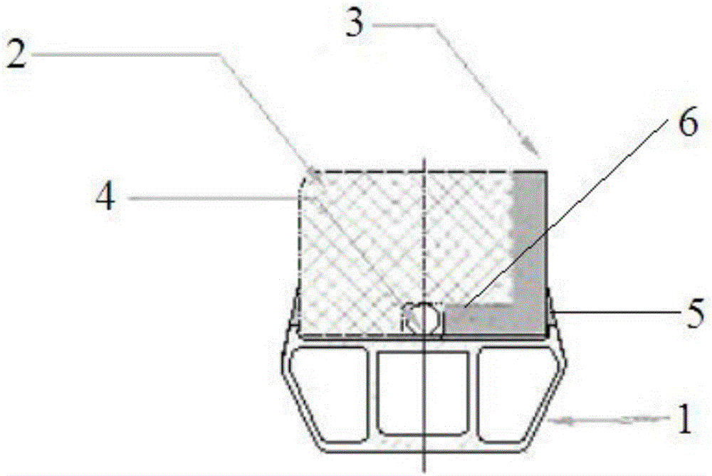
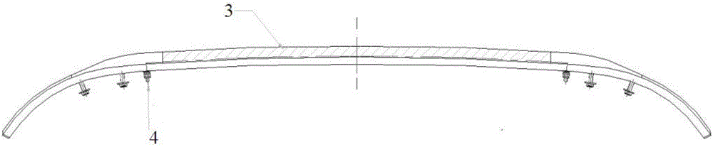
[0023] Such as Figure 1 to Figure 4 As shown, a high-speed EMU pantograph deicing carbon slide plate includes an aluminum bracket 1, a carbon bar 2 and an L-shaped copper plate 3, and the carbon bar 2 and the L-shaped copper plate 3 are fixed on the aluminum bracket 1 On the surface, the L-shaped copper plate 3 is arranged on the front end of the carbon strip 2, and a groove 6 is cut at the bottom of one side of the carbon strip 2, and the short side of the L-shaped copper plate 3 is located in the groove 6 so that one side of the carbon strip 2 presses the L L-shaped copper plate 3, the top of the long side of the L-shaped copper plate 3 is at the same height as the carbon strip 2, and an ADD air channel 4 is also provided inside the carbon strip 2.

[0024] The pantograph deicing carbon slides in this embodiment are double deicing carbon slides, and the installation diagram is as follows Figure 4 shown. The two sides of the upper surface of the aluminum bracket 1 of the ...

Embodiment 2

[0029] Such as Figure 5 to Figure 7 As shown, on the basis of Embodiment 1, the other side of the carbon strip 2 is also provided with an L-shaped copper plate 3, that is, the second L-shaped copper plate 8; the bottom of the other side of the carbon strip 2 is cut with a second groove , the short side of the second L-shaped copper plate 8 is located in the second groove so that the other side of the carbon strip 2 presses the L-shaped copper plate, and the long side top of the second L-shaped copper plate 8 is in contact with the carbon strip 2 at the same height. Such a pantograph deicing carbon slide forms a single deicing carbon slide.

[0030] In the second embodiment, if the width of the aluminum bracket 1 and the carbon strip 2 is increased, it is only necessary to set the L-shaped copper plate 3 on one side of the carbon strip 2, and there is no need to set it on the other side of the carbon strip 2. L-shaped copper plate 3 also can realize the deicing carbon slide ...


PUM


Abstract

The invention discloses a high-speed-motor-train-unit pantograph deicing carbon sliding plate. The high-speed-motor-train-unit pantograph deicing carbon sliding plate comprises an aluminum bracket, a carbon strip and an L-shaped copper plate. The carbon strip and the L-shaped copper plate are fixed on the upper surface of the aluminum bracket, the L-shaped copper plate is arranged on one side of the carbon strip, a groove is cut in the bottom of one side of the carbon strip, the short edge of the L-shaped copper plate is located in the groove to allow one side of the carbon strip to press the L-shaped copper plate, the top of the long edge of the L-shaped copper plate and the carbon strip are located at the same height, and meanwhile an ADD air channel is formed inside the carbon strip. According to the high-speed-motor-train-unit pantograph deicing carbon sliding plate, due to the impact toughness and the good electrical conductivity of a copper material, the carbon strip and a copper alloy material in the carbon sliding plate structure are completely combined, the problem that when railway locomotives and high-speed-motor-train-unit trains suffer from rain and snow weather and greasy weather in all seasons, wires are iced, and running of motor-train-unit trains is influenced is well solved, the safe and normal running of motor train units is guaranteed, and serious pantograph net accidents caused by iced wires are reduced.

Description

technical field [0001] The invention belongs to the field of railway transportation, and relates to a special component for high-speed deicing that affects the operation of the EMU when the railway locomotive and high-speed EMU train encounter rain, snow and fog during winter operation. It is a high-speed EMU pantograph deicing carbon skateboard. Background technique [0002] At present, my country's high-speed rail is developing rapidly, and the technology of high-speed rail has reached the international leading level. Currently, the operating lines are constantly being built and opened to traffic, and they are also involved in the construction of foreign high-speed rail projects. In the 13th Five-Year Plan, the construction of my country's high-speed rail and bullet train lines is still the focus. [0003] Due to the vast territory of our country, the temperature and climate change greatly in four seasons, especially in autumn and winter, the north may start to snow in Oc...

Claims


Application Information

Patent Timeline
Patent Type & Authority Applications(China)
IPC IPC(8): B60L5/20
CPCB60L5/205B60L2200/26
Inventor 凌跃成杨育森虞斌
Owner YIXING CITY YIYANG MEXICAN ROOTS MATERIALS
Why Eureka
Try Eureka