Slag conglomerating and skimming method and device

A slag removal and slag accumulation technology, applied in mechanical cleaning, manufacturing tools, metal processing equipment, etc., can solve the problems of low slag removal efficiency, high loss rate of molten iron, increase energy consumption per ton of steel, etc., and achieve accurate slag accumulation and slag removal. Operation, lower energy consumption, and high slag removal efficiency

Inactive Publication Date: 2017-01-04
BAOSHAN IRON & STEEL CO LTD
View PDF3 Cites 17 Cited by
  • Summary
  • Abstract
  • Description
  • Claims
  • Application Information

AI Technical Summary

Problems solved by technology

[0007] The technical problem to be solved by the present invention is to provide a method and device for collecting slag and removing slag. This solution uses the driving force of the traveling wave magnetic field on the molten iron to make the molten iron slag floating on the upper layer of the molten iron gather at the mouth of the molten iron ladle and automatically overflow out of the molten iron ladle. Slagging operation; the whole process of slagging and slagging is completed under non-contact conditions, which solves the defects of low slagging efficiency and high loss rate of molten iron caused by the large motion inertia of the mechanical slagging machine in the prior art ; At the same time, the non-contact slag removal operation does not have any external devices entering the molten iron, which will not pollute the molten iron, and also avoids the disadvantages of the existing technology that the heat dissipation of the molten iron caused by nitrogen injection, etc., improves the energy consumption per ton of steel

Method used


Image

  • Slag conglomerating and skimming method and device
  • Slag conglomerating and skimming method and device
  • Slag conglomerating and skimming method and device

Examples


Embodiment 1

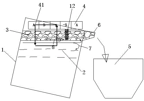
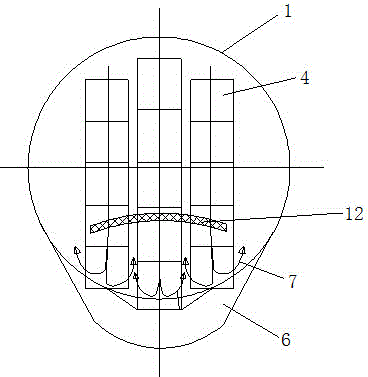
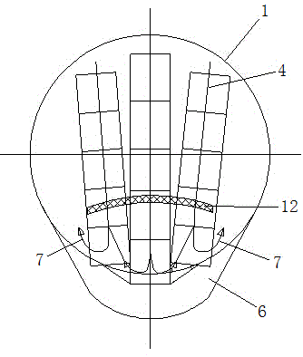
[0027] Such as figure 1 As shown, a method for collecting and removing slag, in which one or more groups of electromagnetic windings 4 are arranged above the ladle 1, through the phase control of the electromagnetic windings 4, the traveling wave magnetic field is excited, and through the control of the phase of the magnetic field, the line The moving direction of the molten iron 2 driven by the wave magnetic field points to the area where the molten iron ladle 6 is located, and the traveling wave magnetic field is used to generate an induced eddy current in the molten iron 2. At this time, the molten iron 2 is equivalent to the moving element of the linear motor, and the induced eddy current is generated in cooperation with the magnetic field. The Lorentz force makes the molten iron in the upper layer of the ladle 1 flow to the mouth of the ladle to form a moving streamline 8. When the molten iron 2 moves along the moving streamline 8 to the wall of the ladle, the backflow aft...


PUM


Abstract

The invention relates to the field of molten iron pretreatment desulfurization processes, in particular to a slag conglomerating and skimming method and a device. The slag conglomerating and skimming method sets a traveling wave magnetic field; the phase of the magnetic field is controlled to enable the moving direction of molten iron driven by the traveling wave magnetic field to point to a ladle port; the traveling wave magnetic field enables the molten iron to flow to the ladle port under the effect of electromagnetic force, so that molten iron slag is conglomerated in the ladle port; and when the conglomerated molten iron slag is higher than the ladle port, the molten iron slag can overflow a ladle to enter a slag receiving tank so as to realize the ladle slag skimming. The slag conglomerating and skimming device comprises an electromagnetic winding and the slag receiving tank; the electromagnetic winding is arranged above the ladle; the magnetic force line of a magnetic field generated by the electromagnetic winding is pointed to an area of the ladle port; and the slag receiving tank is arranged below the ladle port. The slag conglomerating and skimming process is finished under non-contact conditions without generating the molten iron oscillation phenomenon; the molten iron nearly has no loss; the precise slag conglomerating and skimming operation is realized without polluting the molten iron; and the ton steel energy consumption can be reduced.

Description

technical field [0001] The invention relates to the field of molten iron pretreatment desulfurization technology, in particular to a method and device for removing slag from a molten iron ladle. Background technique [0002] The molten iron pretreatment desulfurization process produces a large amount of molten iron pretreatment slag, and the molten iron needs to be treated with ladle slag removal before entering the converter steelmaking process. The traditional first-generation slag removal method uses a reciprocating mechanical mechanism to remove slag. This method has the following main problems: (1) A slag rake is installed at the front end of the mechanical slag remover. Generally, the slag rake must be submerged in the molten iron, which is very difficult. It is difficult to control the submersion depth of the slag rake, and the reciprocating slag rake is likely to have a turbulent effect on the molten iron due to the large inertia of motion, causing the molten iron to...

Claims


Application Information

Patent Timeline
Patent Type & Authority Applications(China)
IPC IPC(8): C21C1/02C21C7/064B22D43/00
Inventor 侯晓光肖永力
Owner BAOSHAN IRON & STEEL CO LTD
Why Eureka
Try Eureka