Manufacturing method of graphite-contained high-speed steel centrifugal composite steel core roller

A technology of centrifugal compounding and high-speed steel, which is applied in the field of high-speed steel centrifugal compounding steel core roll manufacturing, can solve the problems of increased friction coefficient of the roll, affecting the surface quality of the rolled material, and increased wear of the bottom of the groove, so as to improve the surface quality of the rolled material, Improve the overall performance and reduce the effect of increasing the friction coefficient

Active Publication Date: 2017-01-04
SANXIN HEAVY IND MACHINERY
View PDF5 Cites 8 Cited by
  • Summary
  • Abstract
  • Description
  • Claims
  • Application Information

AI Technical Summary

Problems solved by technology

Therefore, during the use of the roll, especially when it is used for the finish rolling product stand, the rolling temperature is low, and the rolling speed is high, the roll base is exposed to the rolling material passing through at low temperature and high speed and the entrainment on the surface of the rolling material. Under the friction of oxide scales, the matrix is ​​preferentially worn and the fulcrum of high-hard carbide is exposed on the surface of the roll, which is specifically manifested in the increase of the surface friction coefficient of the roll (pass type), the decrease of brightness (the phenomenon of roughening), and in severe cases There is steel sticking on the pass surface, which affects the surface quality of rolled products
As a result, the unique anti-wear performance of high-speed steel and the ability to maintain roll shape cannot be effectively exerted, resulting in early roll change
[0003] In addition, when the existing traditional high-speed steel rolls are used in the process of preparing the finished round bar frame with large specifications and high surface quality requirements, due to the deep pass, the inner groove bottom and the groove side of the roll pass The linear velocity difference in different radial directions leads to the relative solid slip (rheology) of the rolled material at the same section, and the huge solid slip produces a file force on the surface of the roll pass, resulting in slippage between the bottom and the side wall of the roll pass. The wrinkle texture is shifted, and the wear of the bottom of the groove is intensified, which affects the precision and surface quality of the rolled material, and cannot fully exert the wear-resistant characteristics of high-speed steel, resulting in early roll change

Method used

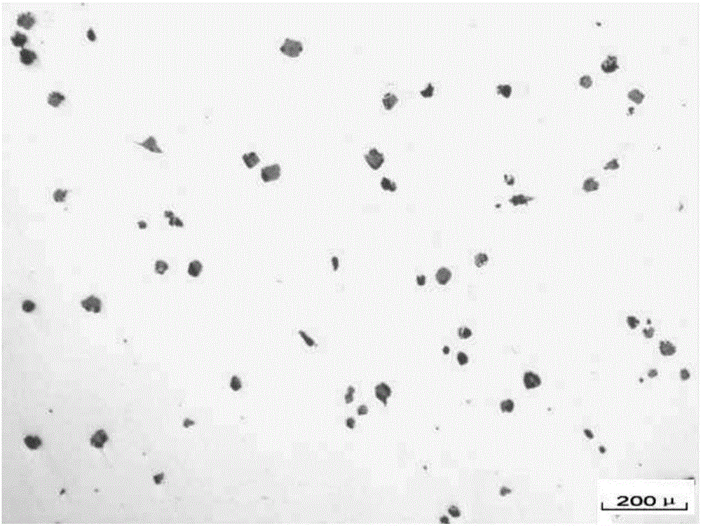
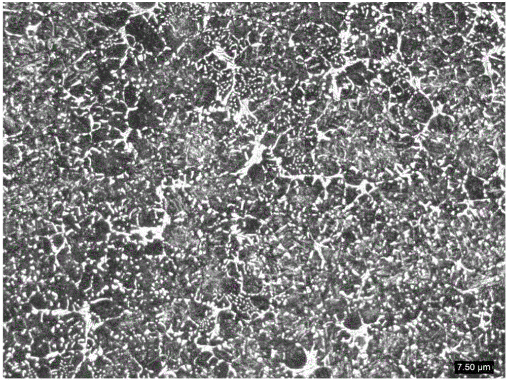
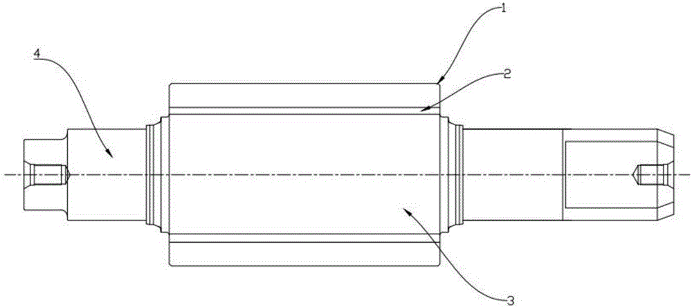

Image

  • Manufacturing method of graphite-contained high-speed steel centrifugal composite steel core roller
  • Manufacturing method of graphite-contained high-speed steel centrifugal composite steel core roller
  • Manufacturing method of graphite-contained high-speed steel centrifugal composite steel core roller

Examples


Embodiment 1

[0034] Embodiment 1 A kind of manufacturing method of the outer shell (working layer) of the centrifugal high-speed steel roll that contains graphite

[0035] 1) The chemical composition of the outer layer is composed by mass fraction (%): C 2.0-3.0%, Si 0.8-2.5%, Mn 0.2-1.0%, 0

[0036] 2) Using intermediate frequency furnace for smelting;

[0037] 3) Si content before furnace control = Si content of finished product - 0.35%; V content before furnace control = V content of finished product - 0.25%;

[0038] 4) Measure the liquid and solidus temperature (T L , T S );

[0039] 5) Control the furnace temperature T 出 = liquidus temperature of the outer metal liquid (T L外 )+(240~300)℃;

[0040] 6) Metamorphic treatment of carbon, nitrogen and borides out of the furnace:

[0041] During the furnace discharge process, along with the metal flow, vanadium alloy ...

Embodiment 2

[0059] Embodiment 2 A kind of manufacturing method of graphite-containing high-speed steel centrifugal steel core composite roll

[0060] Continue with the 10) step of embodiment 1.

[0061] 11) The material of the roller core filling metal liquid is made of carbon-containing C1.2-2.5% semi-steel. Type (including the poured outer cylinder), the inner cavity of the upper roll neck sand mold, and the upper surface of the thermal insulation riser are 300-600mm lower, stop the core pouring, and then add 50-100mm thick thermal insulation agent to the surface of the molten metal in the riser, and stop filling core.

[0062] Replace the high-temperature core-filling molten metal in the same furnace and make some riser preparations. It is required to ensure that the superheat of the molten metal is 80-100°C on the liquidus line of the core-filling metal liquid, that is, T L芯 +(80~100)℃; After stopping the core filling, let it stand still, as time goes by, the temperature of the molt...


PUM

PropertyMeasurementUnit
particle sizeaaaaaaaaaa

Abstract

The invention discloses a manufacturing method of a graphite-contained high-speed steel centrifugal composite steel core roller, and belongs to the field of mechanical casting. Chemical elements of B and N are introduced in a traditional high-speed steel component, MC type and / or M2C type dotted and / or blocky high-hard alloy carbides, nitrides and borides with the total area percentage of 20% to 35% are dispersed and distributed in a work layer base body structure; through carbide, nitride and boride modification, graphite is subject to two-step treatment of modification and inoculation, graphite is precipitated in an original structure, and therefore the high-speed steel roller has the advantages of the specific high-temperature wear resisting of traditional high-speed steel and meanwhile the problem that an original traditional high-speed steel roller is large in friction coefficient is solved; wear-resisting performance of the high-speed steel is fully developed, the lubricating effect between the roller and a workpiece in the rolling process is achieved, and happening of the steel bonding phenomenon is avoided; due to the heat conduction performance and the lubricating characteristic of graphite, the defects that the high-speed steel roller is sensitive to hot impact and hot-cracking susceptibility, steel bonding is prone to happening, and surface roughing is prone to happening can be overcome, and particularly when a finished product rack is used, the surface bright degree of a rolled material is obviously improved.

Description

technical field [0001] The invention relates to a manufacturing method of a graphite-containing high-speed steel centrifugal composite steel core roll, which belongs to the field of mechanical casting. Background technique [0002] The alloy content of the outer layer (working layer) of the existing traditional high-speed steel roll is usually C 1.5-2.5, Si 0.2-0.8, Mn0.4-0.8, P≤0.05, S≤0.02, Cr 4-6, Ni 0.6 -1.5, Mo 3-5, W 0-3, the metallographic structure of the outer layer does not contain graphite, and these alloy elements mainly exist in the form of carbides in the roll structure, and the proportion of carbides is usually 10-20 %between. The proportion of granular alloy carbides is relatively low, and the proportion of matrix area is relatively large. Therefore, during the use of the roll, especially when it is used for the finish rolling product stand, the rolling temperature is low, and the rolling speed is high, the roll base is exposed to the rolling material passi...

Claims


Application Information

Patent Timeline
Patent Type & Authority Applications(China)
IPC IPC(8): C22C38/18C22C38/02C22C38/04C22C38/08C22C38/12C22C38/32B22D13/00B22D19/16B22D1/00B21B27/02
CPCB21B27/02B22D1/00B22D13/00B22D19/16C22C38/001C22C38/02C22C38/04C22C38/08C22C38/12C22C38/18C22C38/32
Inventor 周守行陆怡
Owner SANXIN HEAVY IND MACHINERY
Why Eureka
Try Eureka