Self-positioning internally-installed steel bar U-shaped composite beam

A composite beam, self-positioning technology, applied in the direction of structural elements, building components, long-strip structural components for load-bearing, etc. Cost requirements, do not reflect the huge advantages of steel-concrete structures, etc., achieve significant social and economic benefits, high concrete compressive bearing capacity, and reduce costs.

Inactive Publication Date: 2017-01-04
SHANGHAI RUIYI REAL ESTATE DEV CO LTD
View PDF7 Cites 6 Cited by
  • Summary
  • Abstract
  • Description
  • Claims
  • Application Information

AI Technical Summary

Problems solved by technology

From the published patented technology, the patent number: 2013206125779, only provides a basic method of composite beams. Although compared with the traditional pure steel structure, the steel consumption is reduced a little, but it does not reflect the huge advantages of the joint action of the steel-concrete structure. It does not solve the problems of difficulty in making U-shaped steel beams, complicated installation, and long construction time
From the published patent technology, patent number: 2013100693439 discloses a processing method of J-shaped steel, but the manufacturing process is complicated, the processing cost is high, and the processing time is long, so it is difficult to meet the requirements of processing speed and construction cost in practical applications.

Method used


Image

  • Self-positioning internally-installed steel bar U-shaped composite beam
  • Self-positioning internally-installed steel bar U-shaped composite beam

Examples


Embodiment 1

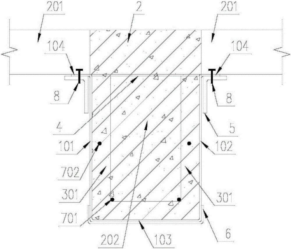
[0020] see figure 1 , the object of the present invention is to provide a self-positioning U-shaped composite beam with built-in reinforcement to overcome the defects in the prior art.

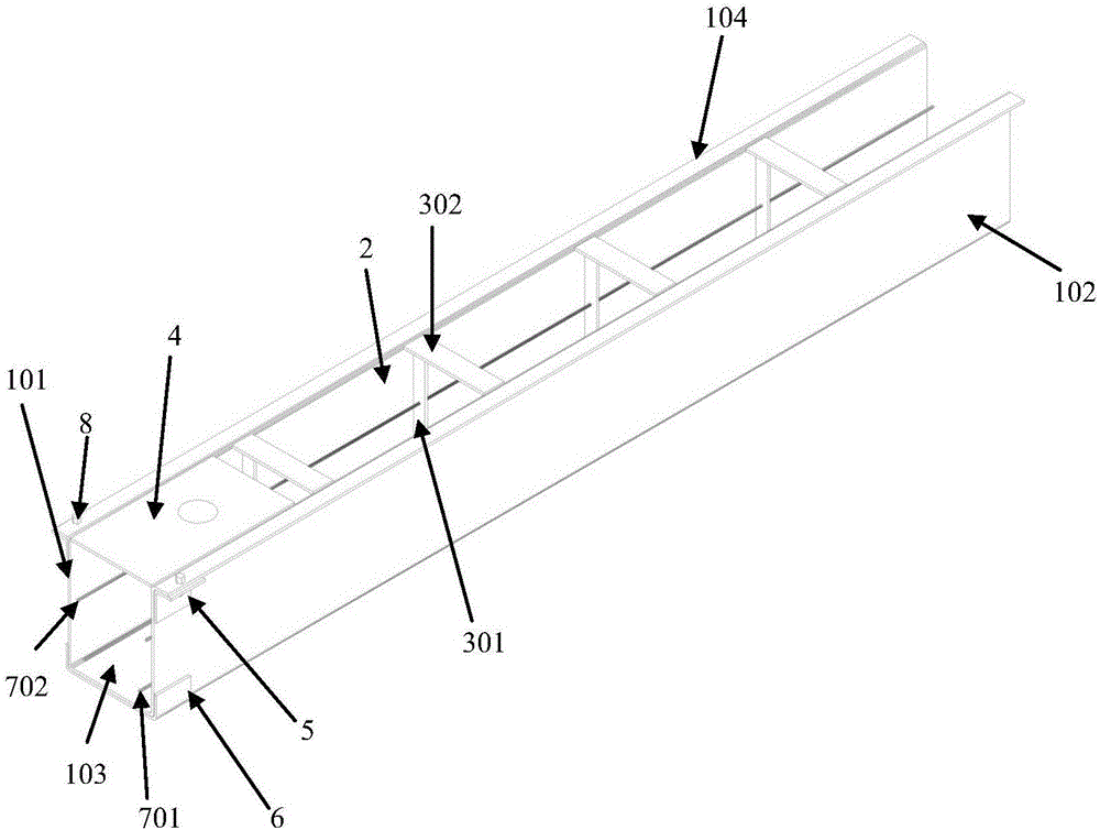
[0021] The U-shaped composite beam includes a U-shaped steel beam shell 1, a concrete girder 2, a reinforcement plate 3 and an upper cover plate 4, angle steel 5, channel steel 6, steel bars 7, and positioning pins 8;

[0022] The U-shaped steel beam shell 1 according to the claims, comprising a left side plate 101, a right side plate 102, a bottom plate 103 and a flange plate 104;

[0023] The bottom of the left side plate 101 and the bottom of the right side plate 102 are respectively connected with the two sides of the bottom plate 103, and are connected into one body, and the end of the flange plate 104 is connected with the left side plate 101 It is integrated with the top of the right side plate 102 and is perpendicular to the left side plate 101 and the right side plate 102;

[0024] ...


PUM

PropertyMeasurementUnit
thicknessaaaaaaaaaa
thicknessaaaaaaaaaa
thicknessaaaaaaaaaa

Abstract

The invention relates to a self-positioning internally-installed steel bar U-shaped composite beam. The self-positioning internally-installed steel bar U-shaped composite beam comprises a U-shaped steel beam housing and concrete components; the middle part of the self-positioning internally-installed steel bar U-shaped composite beam is provided with a U-shaped steel-clad concrete component provided with an opening; each end part of the self-positioning internally-installed steel bar U-shaped composite beam is provided with a rectangular steel-clad concrete component; each beam top flange of a corresponding end part of the self-positioning internally-installed steel bar U-shaped composite beam is provided with a steel angle, a linear upper cover plate is arranged on the beam top flanges, and a groove steel component is arranged on the bottom flanges. The beam end bearing capacity is improved by arrangement of the steel angles, the linear upper cover plate, and the groove steel component, beam torsional stiffness is increased, beam local and entire stability are ensured, installation and construction are convenient, and construction speed is increased greatly. According to the self-positioning internally-installed steel bar U-shaped composite beam, full utilization of the high strength of steel and the high compression bearing capacity of concrete is achieved, steel amount is reduced, cost is reduced, hot rolling or cold rolling is adopted, the self-positioning internally-installed steel bar U-shaped composite beam can be produced via one time moulding, structure deformation caused by welding is reduced, structure reliability is improved, the self-positioning internally-installed steel bar U-shaped composite beam is beneficial for industrial production of steel structures, and excellent social and economic benefit is achieved.

Description

technical field [0001] The invention belongs to the technical field of buildings and relates to a composite steel beam in a building steel structure system. Background technique [0002] Steel beams are important components of buildings, and their performance directly affects the cost and safety performance of buildings. From the published patented technology, the patent number: 2013206125779, only provides a basic method of composite beams. Although compared with the traditional pure steel structure, the steel consumption is reduced a little, but it does not reflect the huge advantages of the joint action of the steel-concrete structure. The problems of difficult fabrication and complicated installation of the U-shaped steel girder and long construction time are not solved. From the published patent technology, patent number: 2013100693439 discloses a processing method of J-shaped steel, but the manufacturing process is complicated, the processing cost is high, and the pro...

Claims


Application Information

Patent Timeline
Patent Type & Authority Applications(China)
IPC IPC(8): E04C3/294E04B5/23
Inventor 陈星朱瑞亮周融夏
Owner SHANGHAI RUIYI REAL ESTATE DEV CO LTD
Why Eureka
Try Eureka