Swirl-type hydraulic ejector with screw spindle

A technology of hydraulic ejector and spiral core, which is applied in the field of oil well fracturing in oil fields, can solve the problems of particle sand concentration, flow rate, and pressure unevenness, so as to solve the problem of unevenness of flushing failure, increase workload and labor intensity, and improve The effect of construction success rate

Active Publication Date: 2017-01-04
BC P INC CHINA NAT PETROLEUM CORP +1
View PDF5 Cites 6 Cited by
  • Summary
  • Abstract
  • Description
  • Claims
  • Application Information

AI Technical Summary

Problems solved by technology

[0003] In order to overcome the serious unevenness of particle sand concentration, flow rate and pressure between the upstream and downstream injectors of the existing double-cluster hydraulic injector, one purpose of the present invention is to propose a swirling flow injector with a spiral mandrel. Hydraulic injector, which uses the thrust / impulse generated when the sand-carrying liquid flows through the spiral channel on the outer surface of the spiral mandrel to drive the spiral mandrel to rotate, thereby forcing the sand-carrying liquid to form a swirl state in the tube, and the swirl flow enters the jet Each nozzle of the injector produces a high-speed jet to achieve the purpose of balancing the sand concentration, flow rate, pressure and high-efficiency perforation and fracturing between the upstream and downstream injectors

Method used


Image

  • Swirl-type hydraulic ejector with screw spindle
  • Swirl-type hydraulic ejector with screw spindle
  • Swirl-type hydraulic ejector with screw spindle

Examples


Embodiment 1

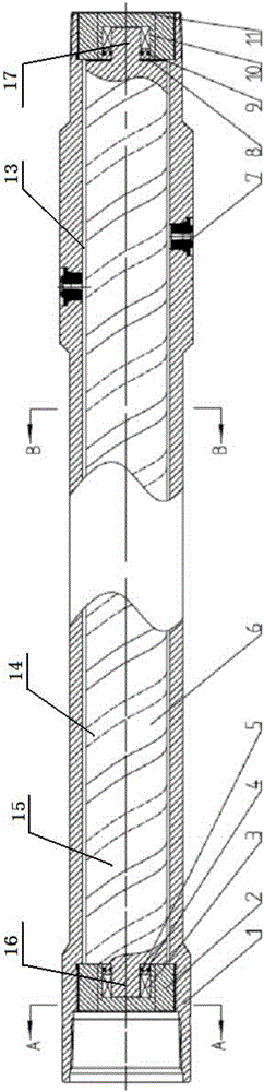
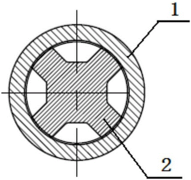
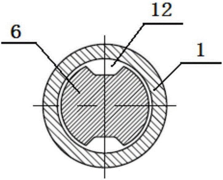
[0029] Such as figure 1 and 2 As shown, a swirling water jet with a spiral mandrel provided by the embodiment of the present invention includes a jet body 1, and a nozzle 7 detachably connected to the side wall of the jet body 1. The injector body 1 has a hollow cavity 12, and a spiral mandrel 6 is arranged inside the hollow cavity 12, and an annular gap for the flow of the sand-carrying liquid is formed between the spiral mandrel 6 and the inner wall of the hollow cavity 12 13; the outer surface of the spiral mandrel 6 is provided with a spiral channel 14 distributed in the form of an Archimedes double helix; the inlet of the sand-carrying liquid of the nozzle 7 is arranged to align with the spiral channel 14, and the nozzle The sand-carrying fluid outlet of 7 is connected to the outer surface of the injector body 1.

[0030] The working principle of the hydraulic ejector of the present invention is: when the sand-carrying liquid flows into the spiral flow channel 14 on the...

Embodiment 2

[0032] On the basis of Example 1, such as figure 1 As shown, the spiral mandrel 6 is a solid shaft made of 35CrMo and heat-treated HBW197-235.

[0033] The length of the spiral mandrel 6 is 1100mm, the outer diameter is 40mm, the length of the injector body 1 is 1300mm, the outer diameter is 100mm, and the inner diameter is 60mm, so the width of the annular gap 13 formed between the injector body 1 and the spiral mandrel 6 It is 20mm, adopting such a small width, so that the sand-carrying liquid flows into each nozzle 7 along the spiral flow channel 14 on the outer surface of the spiral mandrel 6, so as to ensure the sand concentration, The flow and pressure are uniform.

[0034] The upper and lower parts of the injector body 1 are provided with threaded screws, the type of which is 2-7 / 8"EUE, 8 threads per inch, and the taper is 1:16.

Embodiment 3

[0036] On the basis of Example 1, such as image 3 As shown, the spiral flow channel 14 is a trapezoidal groove, a triangular groove or a semicircular groove, preferably a trapezoidal groove, which is convenient for processing.

[0037] The surface of the spiral flow channel 14 is plated with a nickel-based alloy layer to prevent the local erosion of the spiral flow channel 14 caused by the change of the fluid direction.

[0038] The double helix is ​​clockwise, the helix angle is 45°, the pitch of the double helix is ​​120mm, the distance between the double helix is ​​30mm, the length of the spiral trapezoidal groove is 120mm, the depth of the groove is 5mm, the width of the bottom of the groove is 10mm, and the trapezoidal angle is 60°. The spiral flow channel 14 not only meets the specification requirements, but also helps the sand-carrying liquid to form a more suitable outlet velocity and outlet angle of the sand-carrying liquid.

[0039] Example 3

[0040] On the basis...


PUM


Abstract

The invention relates to the technical field of oil field and oil well fracturing, and more specifically relates to a swirl-type hydraulic ejector with a screw spindle. The swirl-type hydraulic ejector comprises an ejector body, and nozzles detachably connected to a sidewall of the ejector body, wherein the ejector body is provided with a hollow cavity in which a screw spindle is disposed; an annular gap for a sand-carrying fluid to flow is formed between the screw spindle and an inner wall of the hollow cavity; a spiral flow channel that presents an Achimedean twin-spiral distribution is formed in an outer surface of the screw spindle; a sand-carrying fluid inlet of each nozzle is disposed as being aligned to the spiral flow channel, while a sand-carrying fluid outlet of each nozzle communicates to an outer surface of the ejector body. The ejector has the characteristics that the screw spindle is driven by thrust / impulsive force generated by a sand-carrying fluid flowing through the spiral flow channel in the outer surface of the screw spindle, such that the sand-carrying fluid is forced to swirl in a pipe to enter into various nozzles of the ejector to generate high-speed jet flows, and therefore, the purpose of reaching equilibrium in sand concentration, flow rate and pressure between upstream and downstream ejectors and the purpose of high effective perforating and fracturing are achieved.

Description

technical field [0001] The invention relates to the technical field of oil well fracturing in an oil field, in particular to a swirling hydraulic injector with a spiral mandrel. Background technique [0002] Nowadays, tight oil and gas reservoirs in some oilfields usually use staged fracturing, clustered perforation, and hydraulic jet fracturing strings for integrated operations of reservoir stimulation, oil testing, and well completion. Among them, the hydraulic jet is the key to implementing the hydraulic jet fracturing process The performance of the tool determines the success of hydraulic jet fracturing construction. At present, due to the staged double-cluster hydraulic jet fracturing construction process, there are serious unevennesses in particle sand concentration, flow rate, and pressure between the upstream and downstream injectors of the dual-cluster hydraulic jet, and the upstream injector cannot shoot through the casing. The casing and formation or the perforat...

Claims


Application Information

Patent Timeline
Patent Type & Authority Applications(China)
IPC IPC(8): E21B43/114E21B43/26
Inventor 仝少凯王祖文白明伟杨小平岳艳芳樊炜温亚魁任荣利张冕徐迎新袁军
Owner BC P INC CHINA NAT PETROLEUM CORP
Why Eureka
Try Eureka