
Cvvt system

A valve timing and variable technology, applied in the direction of valve device, non-mechanical actuated valve, machine/engine, etc., to achieve the effect of improving fuel efficiency and service life

Active Publication Date: 2017-01-04
HYUNDAI MOTOR CO LTD +1
View PDF5 Cites 2 Cited by
  • Summary
  • Abstract
  • Description
  • Claims
  • Application Information

AI Technical Summary

Problems solved by technology

[0012] That is, the intermediate phase CVVT system has an initial position at the intermediate position and retards the intake valve timing when the vehicle is running, so the intermediate phase CVVT of the related art in a manner of controlling the intermediate phase using the cam torque can only be applied to V-type 6-cylinder engine or horizontal engine

Method used


Image

  • Cvvt system
  • Cvvt system
  • Cvvt system

Examples


Embodiment Construction

[0033] The following description is exemplary only and is not intended to limit the invention or its application or uses. It should be understood that throughout the drawings, corresponding reference characters indicate like or corresponding parts and features.

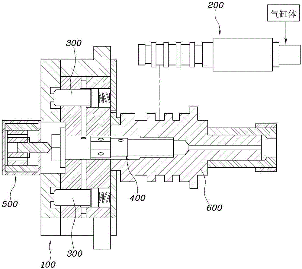
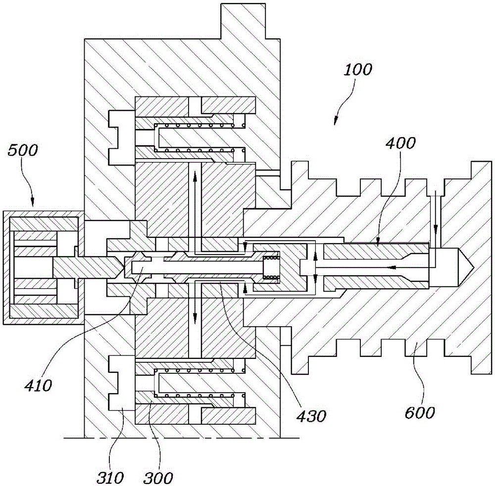
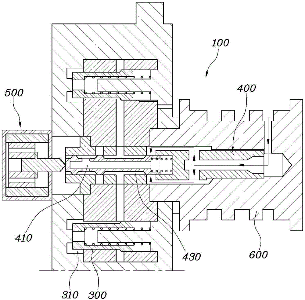
[0034] figure 1 To show a view of a CVVT system in accordance with one form of the present invention, figure 2 with image 3 is a view showing oil flow when the actuator 500 is operating / stopping. Figure 4 To show the view of the lock pin 300 and the lock pin hole 310, Figure 5 is a graph showing the locking speed of the lock pin 300 . Image 6 is a graph showing the advance / retard angles of the intake and exhaust valves. Figure 7 is a diagram showing the overall configuration of the system according to the present invention.

[0035] A continuously variable valve timing (CVVT) system according to an embodiment of the present invention includes: OCV 200 which supplies oil received from a cylinder block to CV...


PUM


Abstract

The present disclosure provides a CVVT system including: an OCV supplying oil received from a cylinder block into a CVVT; an oil supply unit supplying oil from the OCV to a lock pin; and an actuator selectively opening or closing the oil supply unit such that oil is supplied to the lock pin and the lock pin is separated from a lock pin hole when the oil supply unit is opened.

Description

technical field [0001] The present invention relates to a continuously variable valve timing (CVVT) system. Background technique [0002] The statements in this section merely provide background information related to the present disclosure and may not constitute prior art. [0003] Generally, the CVVT system continuously changes opening / closing timing by changing the phase of the camshaft according to the revolutions per minute (RPM) of the engine and the load of the vehicle. In general, a CVVT system mainly includes: a crank angle sensor that senses the rotation angle of the crankshaft, a cam angle sensor that senses the rotation angle of the camshaft, a variable speed sensor that is connected to the side of the camshaft through a timing belt and advances or retards the camshaft. A valve timing unit, and an ECU (Electronic Control Unit) that controls an oil control valve (OCV) so that oil is supplied to the advance chamber of the variable valve timing unit or Hysteresis ...

Claims


Application Information

Patent Timeline
Patent Type & Authority Applications(China)
IPC IPC(8): F01L1/344F01L9/02
CPCF01L1/3442F01L2001/0475F01L2001/0476F01L2001/34433F01L2001/34463F01L2001/34469F01L2001/34466F01L1/34409
Inventor 吴廷翰朴敏秀金允锡
Owner HYUNDAI MOTOR CO LTD
Features
  • Generate Ideas
  • Intellectual Property
  • Life Sciences
  • Materials
  • Tech Scout
  • Unparalleled Data Quality
  • Higher Quality Content
  • 60% Fewer Hallucinations
Learn More