Power transmission using an inscribed cam and a cylindrical pinion

A power transmission device and pinion technology, which is applied in the direction of gear transmission, transmission, belt/chain/gear, etc., can solve the problems of easily increasing friction, reducing transmission capacity, reducing internal gears, etc., and achieving absorption Accuracy error, high transmission capacity, effect of eliminating backlash

Active Publication Date: 2020-11-03
SANKYO SEISAKUSHO
View PDF2 Cites 0 Cited by
  • Summary
  • Abstract
  • Description
  • Claims
  • Application Information

AI Technical Summary

Problems solved by technology

However, when the tip of the tooth is made thinner, the rigidity of the tooth is weakened, and when the height of the teeth of the internal gear and the external gear is reduced, the transmission capacity between the internal gear and the external gear becomes smaller, so the There is a problem with the diameter of the small internal gear
For example, in reducers used in industrial machinery such as robots and belt conveyors, there is a greater problem in order to reduce the reduction ratio to 3 or less.
In addition, when the number of teeth of the internal gear and the external gear is reduced, the friction between the internal gear and the external gear tends to increase, and there is a problem that backlash is likely to occur.
[0007] In addition, since the reducer of Patent Document 2 has outer rollers for the internal gear, it can reduce the friction when the internal gear and the external gear are meshed compared with the reducer of Patent Document 1. Also in the speed reducer, since an external gear having a plurality of external teeth facing radially outward is disposed on the inner peripheral side of the internal gear, the speed reducer of Patent Document 2 also suffers from the same problem as that of the speed reducer of Patent Document 1. question

Method used


Image

  • Power transmission using an inscribed cam and a cylindrical pinion
  • Power transmission using an inscribed cam and a cylindrical pinion
  • Power transmission using an inscribed cam and a cylindrical pinion

Examples


Embodiment Construction

[0056] Hereinafter, examples of the present invention will be described with reference to the drawings, but the present invention is not limited to these examples.

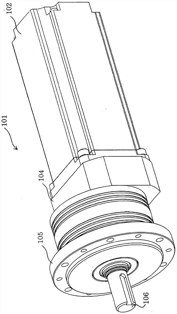
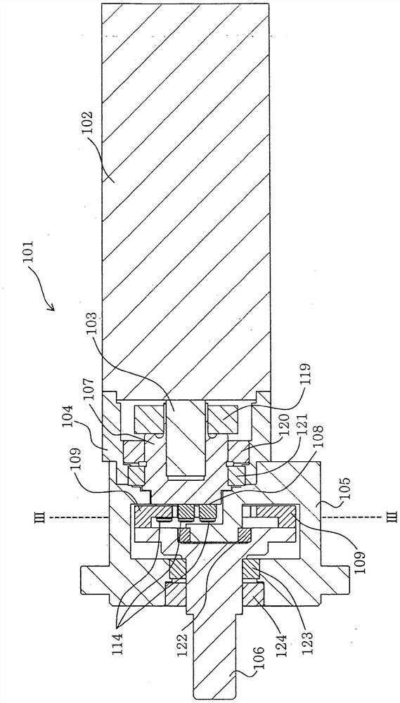
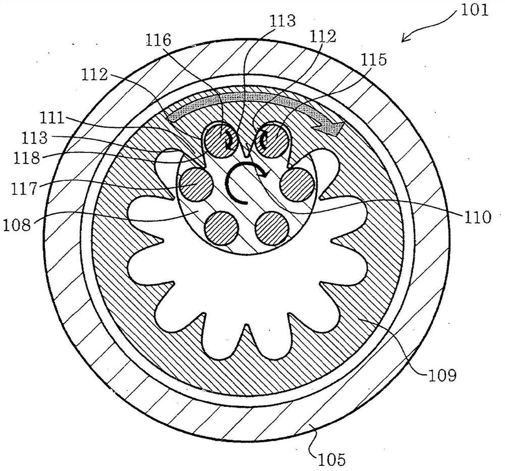
[0057] refer to Figure 1~4 , to describe an embodiment of the power transmission device of the present invention. figure 1 A schematic diagram of the power transmission device 101 is shown. The power transmission device 101 includes an electric motor 102 , housings 104 and 105 , and a rotatable output shaft 106 . figure 2 A cross-sectional view of the power transmission device 101 viewed from the side is shown. The power transmission device 101 includes: an electric motor 102 having a rotatable motor shaft 103; a substantially cylindrical turret 107 having a first end surface 108 and a second end surface, and is connected to the electric motor through a connecting element 119 on the second end surface side. The shaft 103 is connected and rotatable; a plurality of cylindrical pinions 114 are arranged on the turr...


PUM


Abstract

The present invention provides a power transmission device with high transmission capacity, high rigidity, no backlash, high-precision positioning, low friction, and an optimum reduction ratio. The power transmission device (101) includes: a motor (102) having a motor shaft (103); a turret (107) connected to the motor shaft (103); a plurality of cylindrical pinions (114) arranged on the turret (107); ); an inscribed cam (109) with a plurality of internal teeth along the inner surface; an output shaft (106) connected to the inscribed cam (109), wherein a plurality of cylindrical pinions (114) are along the circumferential direction etc. arranged at intervals on the end face (108) of the turret, the cylindrical side of at least one of the plurality of cylindrical pinions (114) contacts the cam surface of at least one of the plurality of internal teeth, This rotates the output shaft (106) connected to the inscribed cam (109).

Description

technical field [0001] The present invention relates to a power transmission device capable of efficiently transmitting rotation of a motor, capable of positioning with high precision, and suitable for long life. Background technique [0002] A power transmission device, especially a speed reducer is a device that outputs power obtained from a power source such as a motor at a reduced rotational speed through gears or the like, thereby obtaining a torque proportional to a reduction ratio. The power transmission device is provided between the device operated by the power transmission device and the power source, and can obtain required torque and rotational speed. The power transmission device is used in, for example, industrial machines such as robots and factory transfer lines, propellers of ships, and propellers of airplanes. [0003] As a power transmission device, Patent Document 1 discloses a speed reduction device including: an internally toothed gear having a plurali...

Claims


Application Information

Patent Timeline
Patent Type & Authority Patents(China)
IPC IPC(8): F16H1/24
CPCF16H1/24
Inventor 今园孝治
Owner SANKYO SEISAKUSHO
Why Eureka
Try Eureka