Supercharge Your Innovation With Domain-Expert AI Agents!

Electronic jacquard solenoid valve component constant current source control device

A solenoid valve assembly, electronic jacquard technology, applied in valve devices, valve operation/release devices, engine components, etc., can solve the problems of many turns, voltage fluctuations, inconvenient daily maintenance, etc., to achieve low input cost, overall simple structure

Active Publication Date: 2018-08-10
常熟纺织机械厂有限公司
View PDF5 Cites 0 Cited by
  • Summary
  • Abstract
  • Description
  • Claims
  • Application Information

AI Technical Summary

Problems solved by technology

[0003] Due to the particularity of textile machinery, the long-term uninterrupted working mode puts forward high requirements on the solenoid valve components. First, the consistency must be good and the action must be clear. In the specific weaving process, the heat dissipation is not timely and the ambient temperature rises. The influence of the resistance of the solenoid valve will be more obvious, which will affect the suction of the solenoid valve; secondly, with the different patterns and the number of needles selected, the load of the power belt will also be different, resulting in voltage fluctuations, which will affect the suction; Further, the existence of the above two reasons will also lead to a shortened life of the solenoid valve assembly, and because of the large number of solenoid valve assemblies, it will cause great inconvenience to daily maintenance
On the other hand, some technical difficulties in the manufacturing process of the solenoid valve assembly will also lead to poor consistency of suction
The solenoid valve assembly is small in size, has a large number of turns, and is wound with variable diameters, so it is easy to cause uneven coil winding, different lengths, and changes in coil resistance, which affect the suction force and make it difficult to achieve consistent suction force

Method used


Image

  • Electronic jacquard solenoid valve component constant current source control device
  • Electronic jacquard solenoid valve component constant current source control device

Examples


Embodiment Construction

[0011] In order to enable the public to fully understand the technical essence and beneficial effects of the present invention, the applicant will describe in detail the specific implementation of the present invention below in conjunction with the accompanying drawings, but the applicant's description of the embodiments is not a limitation to the technical solution. Changes in the form of the inventive concept rather than in substance should be regarded as the protection scope of the present invention.

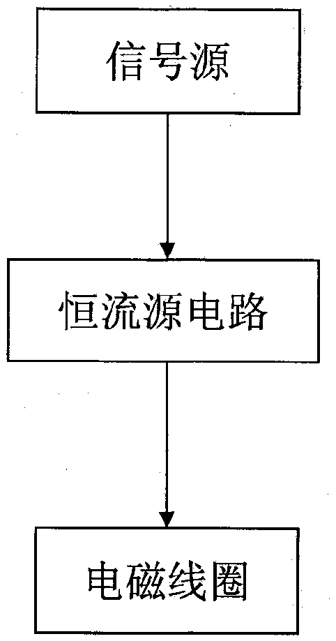
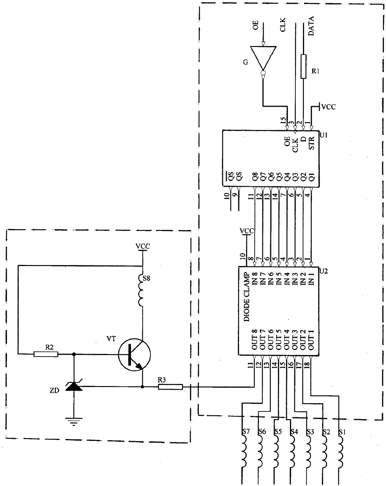
[0012] see figure 1 and figure 2 A constant current source control device for a solenoid valve assembly of an electronic jacquard machine, comprising a signal source and a constant current source circuit, the signal source is connected to the constant current source circuit, and the constant current source circuit is connected to an electromagnetic coil of the solenoid valve assembly. One signal source can correspond to several constant current source circuits, and each con...


PUM


Abstract

The invention discloses a solenoid valve group constant flow source control device for an electronic jacquard machine and belongs to the technical field of electronic jacquard machine parts. The device comprises a signal source and a constant flow source circuit, wherein the signal source is connected with the constant flow source circuit; the constant flow source circuit is connected with a solenoid coil of the solenoid valve group; the signal source comprises a signal processing chip U1, a driver chip U2, a first resistor R1 and a NOT gate G; a pin 2 of the signal processing chip U1 is connected with one end of the first resistor R1; a pin 15 of the signal processing chip U1 is connected with an output end of the NOT gate G; pins 4, 5, 6, 7, 14, 13, 12 and 11 of the signal processing chip U1 are connected with the driver chip U2; pins 11, 12, 13, 14, 15, 16, 17 and 18 of the driver chip U2 are respectively connected with the constant flow source circuit. The solenoid valve group constant flow source control device has the advantages that current flowing through the solenoid valve group is constant, and attraction of the solenoid valve group is invariable, so that the consistency of the solenoid valve group can be improved, and the service life of the solenoid valve group is prolonged.

Description

technical field [0001] The invention belongs to the technical field of electronic jacquard machine components, and in particular relates to a constant current source control device for an electronic jacquard machine solenoid valve assembly. Background technique [0002] The solenoid valve assembly has a needle selection function and is the key actuator of the electronic jacquard machine, usually including a valve seat, an electromagnetic coil and a magnet. The electromagnetic coil is energized, and the upper end of the first jacquard needle is attracted by the magnetic force of the magnetic conductor to deviate, so that the first jacquard needle stops and hangs on the first hook, and then the second jacquard needle that reciprocates up and down drives the second jacquard needle to rise to its position At this time, a warp yarn is lifted in place, and thus the warp yarn shed weaving pattern is formed by selecting needles with the up and down reciprocating motion of the liftin...

Claims


Application Information

Patent Timeline
Patent Type & Authority Patents(China)
IPC IPC(8): F16K31/06
CPCF16K31/0675
Inventor 潘敏彭晓虹濮义欢殷玉兰季静霞陆杨
Owner 常熟纺织机械厂有限公司
Features
  • R&D
  • Intellectual Property
  • Life Sciences
  • Materials
  • Tech Scout
  • Unparalleled Data Quality
  • Higher Quality Content
  • 60% Fewer Hallucinations
Learn More