Blast combustor

A burner and blower technology, which is applied to burners, gas fuel burners, combustion methods, etc., can solve the problems of affecting the application of upper air burners, difficulty in supplementing structural air, and easy occurrence of safety accidents, etc. Long life and good air tightness

Active Publication Date: 2017-01-04
VATTI CORP LTD
View PDF8 Cites 7 Cited by
  • Summary
  • Abstract
  • Description
  • Claims
  • Application Information

AI Technical Summary

Problems solved by technology

For the burner with air intake from above, the primary air and secondary air are all replenished on the upper side of the panel, and the inside of the panel is all sealed pipelines, which can effectively prevent safety accidents caused by tempering, etc. Yellow flames appear, so the heat load of the existing full upper air intake burners is relatively low. This defect seriously affects the application of the upper air intake burner. There is a certain injection distance between them. When there is wind around, the gas may deviate from the gas nozzle, resulting in insufficient injection, and even burning at the gas nozzle.
For the bottom air intake burner, such as the current blast burner, the primary air is supplemented inside the panel, and the secondary air is supplemented on the upper side of the panel. The burner air supplement is relatively sufficient, which is beneficial to the thermal load and thermal efficiency. However, safety accidents are likely to occur when the bottom air intake burner flashes back, and the injection of the bottom air intake burner is carried out inside the panel, which is likely to cause defects such as high internal temperature rise

Method used


Image

  • Blast combustor
  • Blast combustor
  • Blast combustor

Examples


Embodiment Construction

[0032] The present invention will be further described below in conjunction with accompanying drawing:

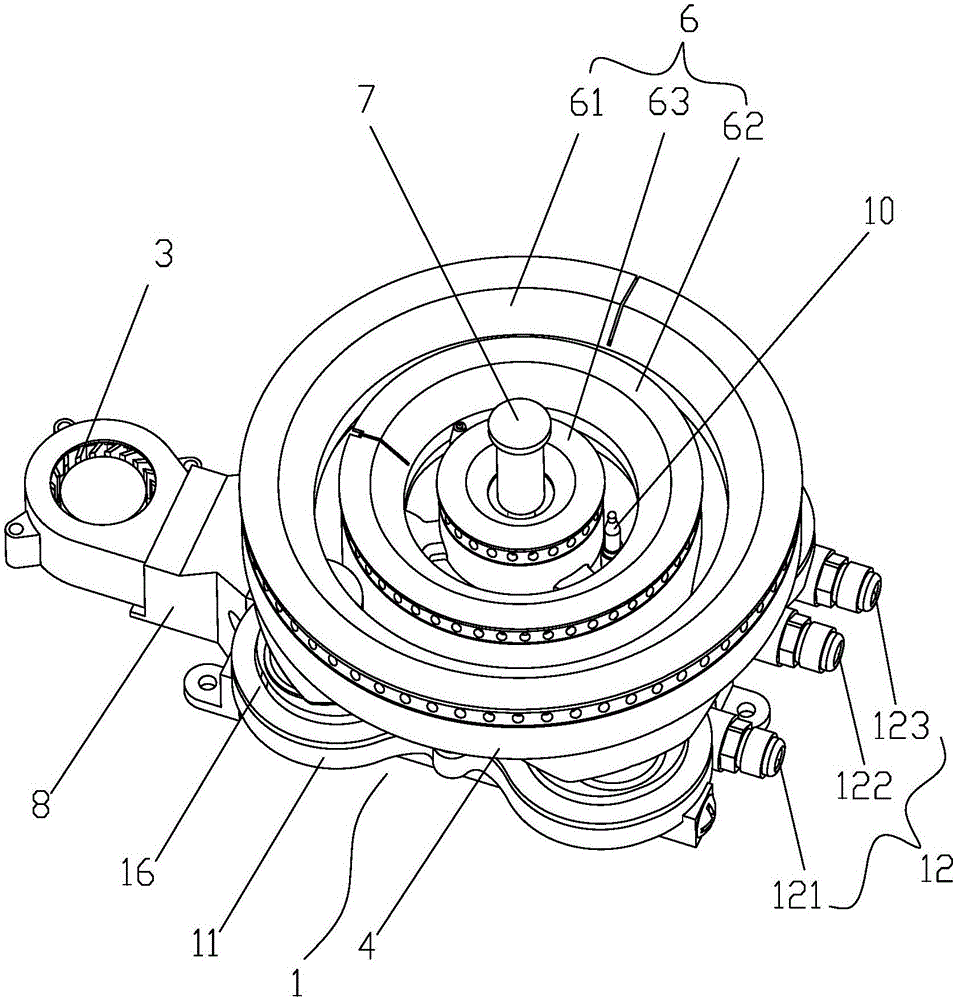
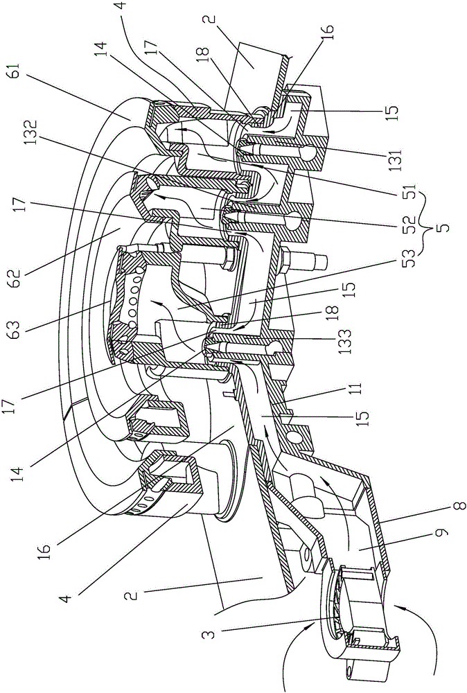
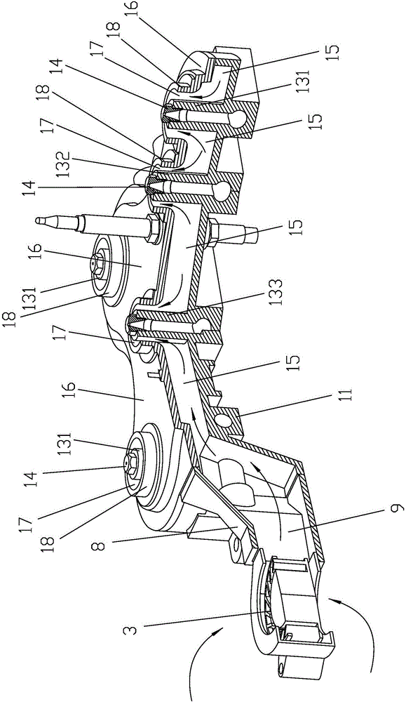
[0033] like Figure 1 to Figure 5 As shown, a blast burner includes a burner 1 and a panel 2 for installing the burner 1, the burner 1 includes a burner base 11, and the burner base 11 is provided with a gas injection The pipe 12 communicates with the gas injection pipe 12 and protrudes from the gas nozzle 13 of the burner base 11. Above the panel 2 is provided with a gas nozzle 14 capable of ejecting the gas in the gas nozzle 13. The burner base 11 is also connected with the burner upper cover 16 surrounding the air flow chamber 15, the burner upper cover 16 is sleeved on the outside of the gas nozzle 13, and the burner upper cover 16 is connected with the An air flow channel 17 communicating with the air flow chamber 15 is formed between the outer walls of the gas nozzle 13, and the burner 1 is connected with a blower 3 that can introduce external air into the air flow c...


PUM


Abstract

The invention discloses a blast combustor. A furnace end base is provided with a gas ejection pipe and a gas spray pipe communicating with the gas ejection pipe and protruding out of the furnace end base; a gas nozzle capable of spraying gas in the gas spray pipe is arranged above a panel; the furnace end base is also connected with an upper furnace end cover defining an air flowing cavity together with the furnace end base; the outer side of the gas spray pipe is sleeved by the upper furnace end cover, and an air flow passage communicating with the air flowing cavity is formed between the upper furnace end cover and the outer wall of the gas spray pipe; a blast blower capable of introducing external air to the air flowing cavity is connected to a furnace end and below the panel; the upper furnace end cover is connected with a distributor on which a mixed gas flow passage capable of allowing air in the air flow passage and gas in the gas nozzle to pass through is arranged on the distributor; and the upper end of the mixed gas flow passage is connected with a fire cover. By using the blast combustor, gas leakage and backfire are effectively avoided, primary air is replenished sufficiently, and the blast blower is far away from the gas nozzle and is low in temperature rise and high in reliability.

Description

[0001] 【Technical field】 [0002] The present invention relates to a burner, more particularly to a blast burner. [0003] 【Background technique】 [0004] Present embedded gas cooker mainly adopts two kinds of full upper air intake burner or full lower air intake burner. For the burner with air intake from above, the primary air and secondary air are all replenished on the upper side of the panel, and the inside of the panel is all sealed pipelines, which can effectively prevent safety accidents caused by tempering, etc. Yellow flames appear, so the heat load of the existing full upper air intake burners is relatively low. This defect seriously affects the application of the upper air intake burner. There is a certain injection distance between them. When there is wind around, the gas may deviate from the gas nozzle, resulting in insufficient injection, and even burning at the gas nozzle. For the bottom air intake burner, such as the current blast burner, the primary air is s...

Claims


Application Information

Patent Timeline
Patent Type & Authority Applications(China)
IPC IPC(8): F23D14/04F23D14/46F23D14/64F23D14/82
CPCF23D14/04F23D14/46F23D14/64F23D14/82F23D2203/007
Inventor 吴谢军张喜杰杨杰潘叶江
Owner VATTI CORP LTD
Why Eureka
Try Eureka