
Fire grate and manufacturing method thereof

A manufacturing method and grate technology, which is applied in the direction of combustion method, grate, incinerator, etc., can solve the problems of fracture and damage, accidental damage of grate installation, etc., and achieve the effect of cost reduction and cost reduction

Inactive Publication Date: 2017-01-04
EBARA ENVIRONMENTAL PLANT +1
View PDF8 Cites 0 Cited by
  • Summary
  • Abstract
  • Description
  • Claims
  • Application Information

AI Technical Summary

Problems solved by technology

Therefore, during the operation of the incinerator, non-combustible materials in the waste may be bitten between the components of the hearth, resulting in breakage accidents, or accidental damage when installing the grate.

Method used


Image

  • Fire grate and manufacturing method thereof
  • Fire grate and manufacturing method thereof
  • Fire grate and manufacturing method thereof

Examples


Embodiment Construction

[0050] Hereinafter, embodiments of the present invention will be described with reference to the drawings. In the drawings described below, the same reference numerals are assigned to the same or corresponding components, and overlapping descriptions will be omitted.

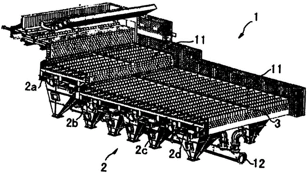
[0051] figure 1 It is an overall view showing the hearth part of the motorized grate type incinerator using the grate of this embodiment. As shown in the figure, the motorized grate incinerator 1 includes a hearth portion 11 having a stepped structure as a whole. The hearth part 11 is arranged with multi-layer motorized grates 2 . The motorized grate 2 has a drying area 2a, a first combustion area 2b, a second combustion area 2c, and a post-combustion area 2d along the moving direction of the object to be incinerated.

[0052] The hearth portion 11 has a partition 3 at a central portion in the width direction. exist figure 1 In the example shown, the motorized grate type incinerator 1 is provided with one...


PUM


Abstract

The invention provides a fire grate and a manufacturing method thereof. The fire grate is made of a marketable material or is made of a part which has the uniform thickness, the high casting accuracy and the simple shape. The fire grate is used in an incinerator and comprises a first alloy steel material and a second alloy steel material different from the first alloy steel material.

Description

technical field [0001] The invention relates to a fire grate and a method for manufacturing the fire grate. Background technique [0002] Conventionally, a motorized grate type incinerator is known as an incinerator in a waste treatment facility for detoxifying hazardous substances generated during incineration treatment of waste. The mobile grate type incinerator has a fixed furnace array and a movable furnace array arranged side by side along the width direction of the incinerator. The array of fixed furnaces and the array of movable furnaces are arranged alternately in a stepwise manner along the longitudinal direction of the incinerator (the transfer direction of the object to be incinerated). [0003] In recent years, a large number of waste treatment facilities have additionally installed boilers and turbine generators to function as power plants that generate electricity as heat recovery facilities in addition to the incineration treatment function. Power plants nee...

Claims


Application Information

Patent Timeline
IPC IPC(8): F23H11/10F23G5/44
Inventor 浦上嘉信冈武裕有原元史张文渊田书营王泰山
Owner EBARA ENVIRONMENTAL PLANT
Learn More