In-machine roundness detection method

A detection method and technology of cylindricity, which is applied in the field of on-machine detection of cylindricity, can solve problems such as inability to give cylindricity error, high requirements for the measurement environment, and high price, so as to avoid multiple clamping, expand the range of clamping, The effect of improving adaptability

Inactive Publication Date: 2017-01-04
BEIJING INSTITUTE OF TECHNOLOGYGY
View PDF6 Cites 11 Cited by
  • Summary
  • Abstract
  • Description
  • Claims
  • Application Information

AI Technical Summary

Problems solved by technology

The equipment for measuring cylindricity error in actual production includes cylindricity meter, three-coordinate measuring machine, etc. The cylindricity meter has high measurement accuracy, but is expensive, and has high requirements on the measurement environment, so its application is limited; commonly used in laboratories and factories The cylindricity error is measured by a three-coordinate measuring machine. When the three-coordinate measuring machine is used to measure the cylindricity error, a series of coordinate values ​​of discrete measuring points are obtained. Data processing is required to solve the cylindricity error, but the current three-coordinate measuring machine only gives The cylindricity error of the least squares fitting, but the cylindricity error of the minimum area method cannot be given. In addition, the current cylindricity measurement device can only perform offline measurement, which requires positioning, poor accuracy, low efficiency, and repeated clamping and positioning. Introduce a new measurement error, which brings inconvenience to the measurement

Method used


Image

  • In-machine roundness detection method
  • In-machine roundness detection method
  • In-machine roundness detection method

Examples


Embodiment Construction

[0035] The present invention will be described in detail below in conjunction with the accompanying drawings and specific examples.

[0036] Such as Figure 1-8 Shown, a kind of cylindricity on-machine detection method of the present invention adopts steps as follows:

[0037] ①Use the rotating device to clamp the measured cylinder 14, and establish the workpiece coordinate system based on the three-coordinate measuring machine;

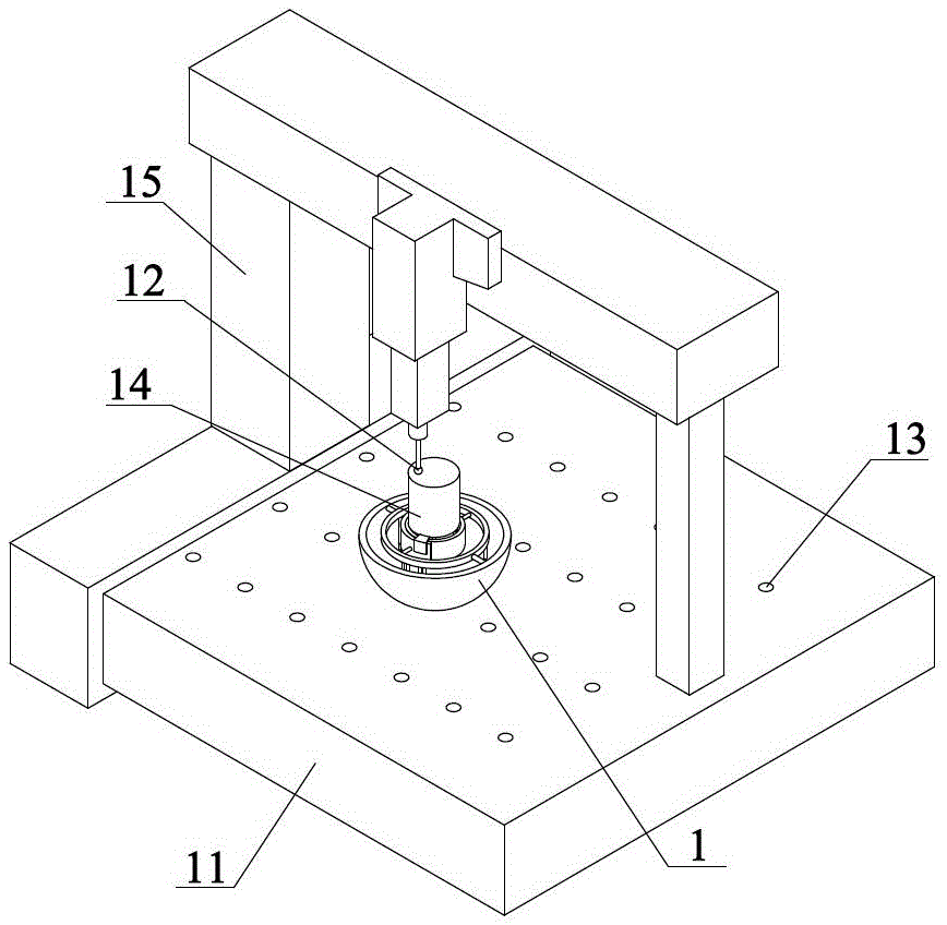
[0038] 101 Start the three-coordinate measuring machine, move the column 15 arranged on the workbench 11 to calibrate the radius of the probe 12;

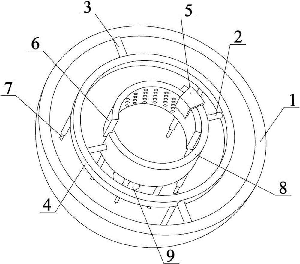
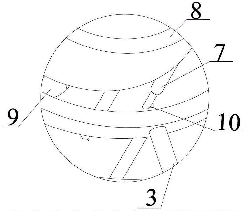
[0039] 102 Set the cylinder 14 in the rotating device, the rotating device includes: a base 1, a first rotating shaft 2, a second rotating shaft 3, a hoop 4, a buckle 5, a first half ring 8 and a second half ring 6; The first half ring 8 is set on the hoop 4 through the first rotating shaft 2 , the second half ring 6 is connected with the first half ring 8 through the buckle 5 , and the hoop 4 is set on...


PUM


Abstract

The invention relates to the field of machining and detection, in particular to an in-machine roundness detection method. The in-machine roundness detection method involves a base, a first rotating shaft, a second rotating shaft, a circular hoop, a clamping buckle, a first half ring and a second half ring, wherein the first half ring is arranged on the circular hoop through the first rotating shaft; the second half ring is connected with the first half ring through the clamping buckle; the circular hoop is arranged on the base through the second rotating shaft; supporting legs are arranged on the lower end surfaces of the circular hoop and the first half ring. According to the in-machine roundness detection method, a three-dimensional measurement point, acquired by a three-coordinate measurer, on a cylinder is projected to a plane, and a circle center of a circle with the minimum area is searched by an iteration method, so that the calculated amount of searching is greatly simplified; an initial value of the circle center is determined by the least square method according to the projected measurement point, so that the search process under a determined attitude is quicker; by the selection of a center moving direction and a center moving step length, the number of searching times is reduced, and the searching precision is improved.

Description

technical field [0001] The invention relates to the field of mechanical processing and detection, in particular to an on-machine detection method for cylindricity. Background technique [0002] Cylindrical surface is a geometric element that is widely used in the design and processing of mechanical parts. The cylindricity tolerance is the accuracy requirement for the shape of this geometric element, and it is one of the main geometric errors that need to be detected and controlled in precision machining. . The cylindricity of the workpiece is the minimum distance that the cylindrical surface is contained in two coaxial cylindrical surfaces. In production, the roundness tolerance of the cylindrical section and the straightness tolerance of the prime line (or axis) are generally used to control the cylindricity error, or the radial runout tolerance is used to control the cylindricity error. These two control methods cannot be actually measured and calculated. The size of the...

Claims


Application Information

Patent Timeline
Patent Type & Authority Applications(China)
IPC IPC(8): G01B21/20
CPCG01B21/20
Inventor 刘志兵王峻青王东前王西彬籍永建焦黎闫正虎潘霖梁志强颜培冷寿阳张路
Owner BEIJING INSTITUTE OF TECHNOLOGYGY
Why Eureka
Try Eureka