Eureka AIR delivers breakthrough ideas for toughest innovation challenges, trusted by R&D personnel around the world.

Sample for measuring high temperature fracture toughness and preparation method thereof

A technology of fracture toughness and high temperature, which is applied in the field of measuring high temperature fracture toughness samples and its preparation, which can solve the problems of easy sintering of fastening screws, cumbersome preparation process, and low positioning accuracy, so as to ensure accuracy and effectiveness , The processing technology is simplified, and the effect of easy clamping on the machine

Inactive Publication Date: 2017-01-04
AECC AVIATION POWER CO LTD
View PDF5 Cites 1 Cited by
  • Summary
  • Abstract
  • Description
  • Claims
  • Application Information

AI Technical Summary

Problems solved by technology

Fix the positioning baffle on the sample with fastening screws. This kind of sample preparation requires processing two threaded holes on the sample and processing two positioning baffles. Fix the positioning baffle on the sample with fastening screws. on, and the fastening screws are easy to sinter at high temperature, causing the screws and baffles to be used only once
The sample preparation process is cumbersome. Due to the positioning error of the threaded hole, the processing error of the positioning baffle, and the assembly error, the positioning accuracy after clamping the COD gauge is low, which affects the accuracy of the test.

Method used


Image

  • Sample for measuring high temperature fracture toughness and preparation method thereof
  • Sample for measuring high temperature fracture toughness and preparation method thereof
  • Sample for measuring high temperature fracture toughness and preparation method thereof

Examples


Embodiment Construction

[0035] The present invention will be described in further detail below in conjunction with the accompanying drawings.

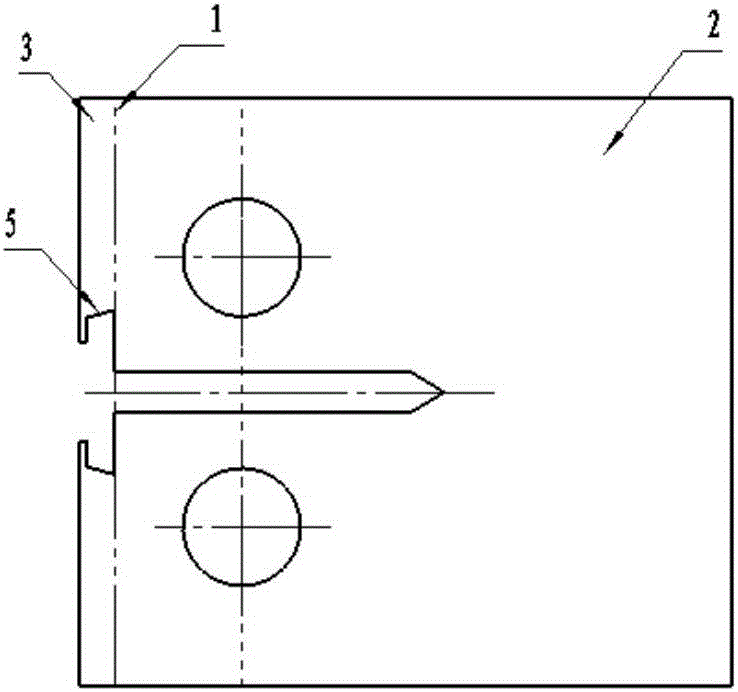
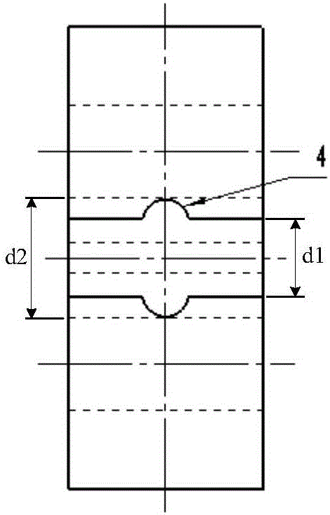
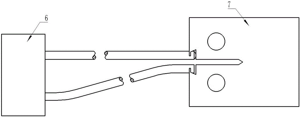
[0036] refer to figure 1 , figure 2 and image 3 , the sample 7 of the present invention includes a sample body 2, the left end of the sample body 2 is provided with a gap, the gap runs through the front and rear sides of the sample body 2, and on the upper and lower sides of the gap, the sample body 2 is respectively provided with symmetrical through hole.

[0037] The present invention takes figure 1 The left, right, up, and down directions are defined as shown, that is, the end where the notch in the sample body 2 is located is the left end, which is only for describing the present invention more clearly, rather than limiting the present invention.

[0038] An auxiliary dividing line 1 is set on the front side of the left end of the sample body 2, and on the left side of the auxiliary dividing line 1, an additional knife edge 3 is integrally provided ...


PUM


Abstract

The invention relates to a sample for measuring high temperature fracture toughness and a preparation method thereof. The sample comprises a sample body with a gap in the left end, the left end of the sample body is connected with an additional cutter point, a line cutting groove is formed in the additional cutter point, and the line cutting groove penetrates through the additional cutter point and is communicated with the gap. The upper side edge and the lower side edge of the line cutting groove are connected with locating baffles respectively, and a T-shaped structure is formed. The locating baffles are oppositely arranged, and cutter point locating grooves are formed in the middles of the locating baffles respectively. The compact tensile sample capable of being used for the metal material fracture toughness testing experiment under high-temperature conditions, the line cutting groove is formed, and therefore the sample and a high-temperature COD gauge can be clamped and matched conveniently. The cutter point locating grooves are formed, so that the situation that due to the fact that the high-temperature COD gauge slides and even slides out, the experiment is not precise or fails is avoided. Due to the fact that the additional cutter point and the sample are integrally machined, the assembly problem before the experiment is avoided, therefore, the sample can be clamped on a machine conveniently, meanwhile, the clamping precision of the sample is guaranteed, and finally the accuracy and effectiveness of the experiment of the sample are guaranteed.

Description

[0001] 【Technical field】 [0002] The invention relates to the field of material testing, in particular to a sample for measuring high-temperature fracture toughness and a preparation method thereof. [0003] 【Background technique】 [0004] At present, the samples for high temperature fracture toughness tests at home and abroad usually adopt the following two forms: [0005] (1) The sample without the positioning device specified by COD. This kind of sample is directly clamped without limit in the test. During the test, the COD gauge is likely to slip or even slip out, causing the test to be inaccurate or fail; [0006] (2) Samples with a COD-specified positioning device. Fix the positioning baffle on the sample with fastening screws. This kind of sample preparation requires processing two threaded holes on the sample and processing two positioning baffles. Fix the positioning baffle on the sample with fastening screws. On, and the fastening screw is easy to sinter at high ...

Claims


Application Information

Patent Timeline
IPC IPC(8): G01N3/18G01N1/28
CPCG01N3/18G01N1/286G01N2001/2873
Inventor 李跃辉郭子静张琳娜吕建勋陈林洪张彩珍孙玉龙吴同战
Owner AECC AVIATION POWER CO LTD
Why Eureka
Eureka Blog
Learn More