Test system and test method for accelerating optical damp-heat aging for optical high molecular material

A polymer material, damp heat aging technology, applied in the direction of analysis materials, measuring devices, scientific instruments, etc., can solve the problems of high test cost and lack of universality of measurement data, and achieve shortening of aging time, effective blue light radiation total amount, The effect of simple structure

Pending Publication Date: 2017-01-04
CHANGZHOU INST OF TECH RES FOR SOLID STATE LIGHTING
View PDF6 Cites 13 Cited by
  • Summary
  • Abstract
  • Description
  • Claims
  • Application Information

AI Technical Summary

Problems solved by technology

The measurement results obtained by this method are greatly affected by the performance of the LED chip and the processing technology of the packaged device, so the aging performance of the LED optical components can only be measured indirectly
In addition, the measurement data obtained by this method is not universal. When the LED chip or packaging process changes, the surrounding environment of the LED optical components also changes, and the aging performance of the LED optical polymer material needs to be re-measured.
On the other hand, because LED optical polymer materials are mostly made of silica gel and have good chemical stability, direct testing of them by high temperature or high temperature and high humidity methods often requires thousands of hours of testing time, and the testing cost is huge, so it is not recommended for enterprises. use

Method used


Image

  • Test system and test method for accelerating optical damp-heat aging for optical high molecular material
  • Test system and test method for accelerating optical damp-heat aging for optical high molecular material
  • Test system and test method for accelerating optical damp-heat aging for optical high molecular material

Examples


Embodiment Construction

[0032] The present invention will be further described below in conjunction with the examples, but the protection scope of the present invention is not limited only to the examples.

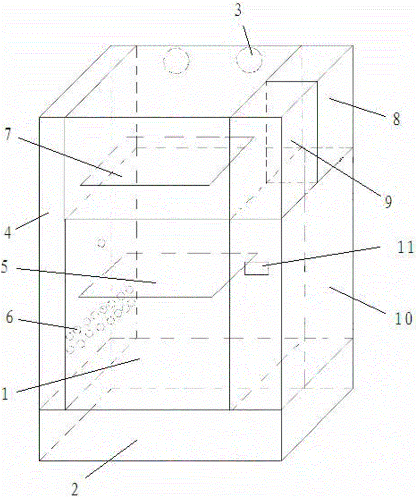
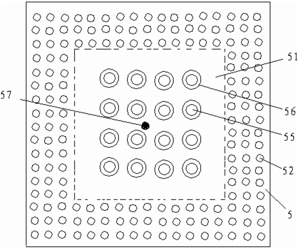
[0033] combine figure 1 As shown, a photomoisture-heat aging accelerated test system for optical polymer materials has a constant temperature and humidity test box 1, the side of the constant temperature and humidity test box 1 is provided with a test hole 6, and the outside of the constant temperature and humidity test box 1 is equipped with There is an iron cover 4 to improve the stability of the test conditions. The inner surface of the constant temperature and humidity test chamber 1 is coated with a layer of light-absorbing material, and a blue light source panel 7 is arranged inside the constant temperature and humidity test chamber, and the blue light source panel 7 is close to the top of the constant temperature and humidity test chamber 1. A plurality of luminous light sources are evenl...


PUM

PropertyMeasurementUnit
diameteraaaaaaaaaa

Abstract

The invention discloses a test system and a test method for accelerating optical damp-heat aging for an optical high molecular material. Through a constant temperature and humidity test chamber of which the inner surface is coated with an optical absorption material layer, a blue light source panel is arranged inside the constant temperature and humidity test chamber, an object accommodating shelf is arranged below the blue light source panel, the upper surface and lower surface of the object accommodating shelf are provided with optical absorption material layers respectively, and a fan is arranged above the blue light source panel; a controller for controlling the blue light source panel to work and a driving device are arranged on one side of the blue light source panel, an object accommodating area is arranged at the center of the blue light source panel, and uniformly distributed through holes are formed in the periphery of the object accommodating area; and the object accommodating shelf is welded with a photometric probe support, and a fixed ring for placing a photometric probe is arranged at the upper end of the photometric probe support. The test system has the advantages that the temperature and humidity of a sample cannot be fluctuated by environmental influence, the surface of the sample cannot be stressed, and the position is constant in the test process. Blue light is prevented from being reflected and radiated on the sample from the rear part, so that the accuracy of a test result is improved.

Description

technical field [0001] The invention relates to the related technical field of optical polymer material testing equipment, in particular to a photomoisture-heat aging accelerated testing system and testing method for optical polymer materials. Background technique [0002] At present, the vast majority of white LEDs on the market use blue light chips to excite phosphors to produce white light. The optical polymer materials (such as fluorescent glue and silicone lenses) inside these LED devices will slowly age, and in severe cases, they will appear yellowing, Browning or blackening. These phenomena will aggravate the light decay and color drift of LED packaging devices, resulting in a rapid decline in service life. [0003] The optical polymer material of the white light LED packaging device is often close to the LED chip. During the use of the LED packaging device, the increase in the junction temperature of the LED chip will increase the temperature of the optical polymer ...

Claims


Application Information

Patent Timeline
Patent Type & Authority Applications(China)
IPC IPC(8): G01N17/00
CPCG01N17/00G01N17/004
Inventor 钱诚吝凯叶怀宇樊嘉杰文康樊学军张国旗
Owner CHANGZHOU INST OF TECH RES FOR SOLID STATE LIGHTING
Why Eureka
Try Eureka