
Device and method for detecting optical fiber con-focal dynamic Raman spectra

A Raman spectrum and detection device technology, applied in the field of laser detection, can solve problems such as the steady-state spectrum of the measured substance that does not have time resolution ability, and achieve the effect of time resolution ability

Inactive Publication Date: 2017-01-04
INST OF FLUID PHYSICS CHINA ACAD OF ENG PHYSICS
View PDF11 Cites 5 Cited by
  • Summary
  • Abstract
  • Description
  • Claims
  • Application Information

AI Technical Summary

Problems solved by technology

[0003] The purpose of the present invention is to overcome the problem that the traditional Raman spectrum detection device in the prior art can only obtain the steady-state spectrum of the measured substance without time resolution capability, and to provide a Raman spectrum detection device with time resolution capability

Method used


Image

  • Device and method for detecting optical fiber con-focal dynamic Raman spectra

Examples


Embodiment 1

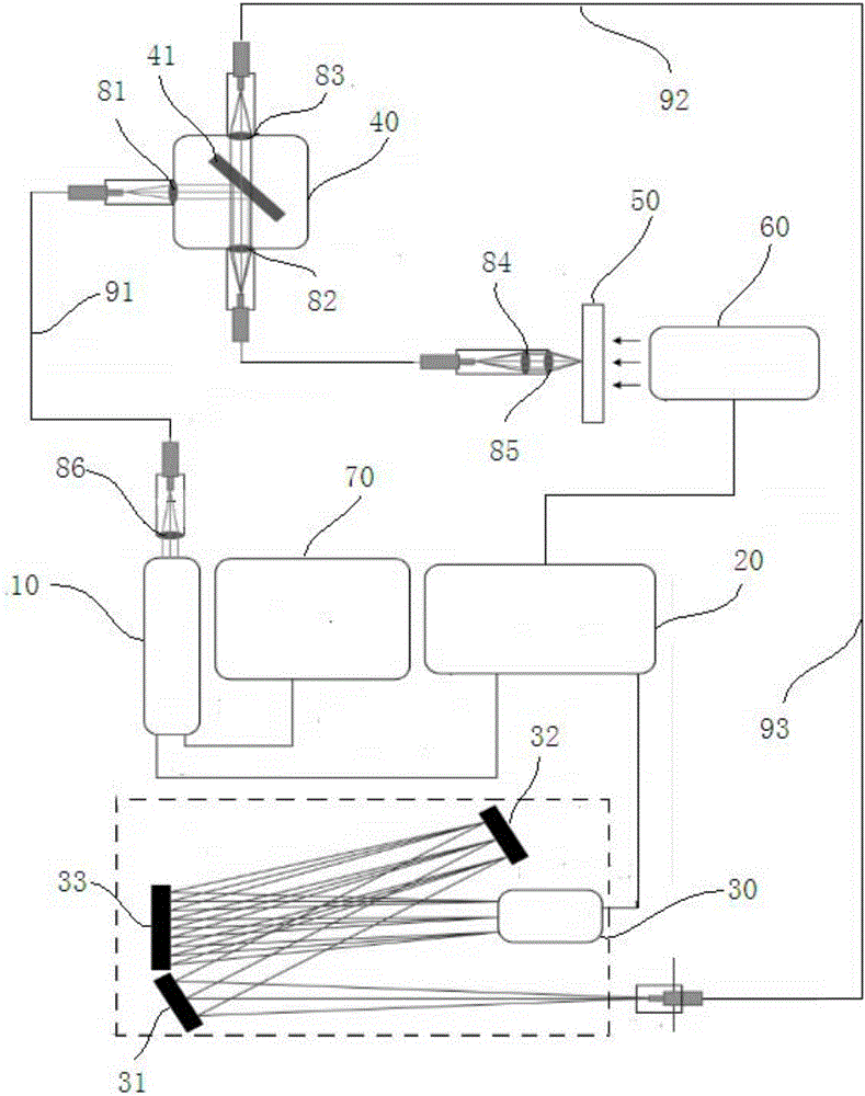
[0027] Embodiment 1: as figure 1 As shown, this embodiment provides a fiber optic confocal dynamic Raman spectroscopy detection device, including,

[0028] The laser 10 is used to emit a detection laser with a specified wavelength;

[0029] The spectrum collection device 30 is used to receive the Raman signal light reflected back from the measured substance 50; specifically, the ICCD detection array can be a preferred spectrum collection device;

[0030] A synchronous control device 20, configured to receive a trigger signal from the excitation source 60, and synchronously trigger the laser 10 and the spectrum collection device 30;

[0031] The optical fiber cross-border device is respectively connected to the laser 10, the measured substance 50 and the spectrum collection device 30 through the first optical fiber 91, the second optical fiber 92 and the third optical fiber 93; it is used to receive the detection laser emitted from the laser 10, and transmit the The detection...

Embodiment 2

[0038]Embodiment 2: The present invention also provides a Raman spectrum detection method with time resolution capability. Specifically, a pulse trigger method is adopted to synchronously trigger the laser 10 to emit detection laser light, the excitation source 60 to emit the excitation light source, and the spectrum collection device 30 to receive the Raman signal Light; the excitation source 60 may be an excitation light source, an impact loading source (such as an air cannon), or an ultrasonic loading source (such as an ultrasonic transducer). .

[0039] Preferably, the excitation source 60 sends a trigger signal to the synchronous control device 20 , and the synchronous trigger device synchronously controls the opening of the laser 10 and the spectrum collection device 30 .

[0040] Preferably, the synchronous triggering device is a delay generator, and the delay generator adjusts the turn-on time of the laser 10 and the spectrum collection device 30 according to the trigg...


PUM


Abstract

The invention relates to the field of laser detection, in particular to a device and a method for detecting optical fiber con-focal dynamic Raman spectra. The device and the method for detecting the optical fiber con-focal dynamic Raman spectra, provided by the invention, have the benefits that pulse laser is adopted as a light source for generating a Raman signal to replace continuous laser in a traditional Raman detection device, and the triggering time of a laser and the triggering time of an optical spectrum collecting device are synchronized; the time resolution ability is realized through adjusting delay time between the triggering time and the triggering time of an excitation source excited by a detected substance; meanwhile, the device couples first optical fibers connected with the laser, second optical fibers connected with the end of the detected substance and a third optical fiber connected with an optical spectrum detection device together by using an optical fiber jumper device, and a laser excitation light path and a Raman signal collecting light path are completed through connection.

Description

technical field [0001] The invention relates to the field of laser detection, in particular to an optical fiber confocal dynamic Raman spectrum detection device and a detection method. Background technique [0002] Raman spectrum is a kind of scattering spectrum. Raman spectroscopy is an analysis method based on the Raman scattering effect to analyze the scattering spectrum different from the incident light frequency to obtain the molecular vibration and rotation information of the measured substance, and to apply it to the study of material structure and material properties. However, traditional Raman spectroscopy detection devices mostly use continuous laser light to detect the steady-state spectrum of the measured substance, which does not have the ability to resolve time; and for some Raman spectroscopy application scenarios, some properties of the measured substance (including Not limited to the temperature, external pressure, molecular structure, crystal structure, ph...

Claims


Application Information

Patent Timeline
IPC IPC(8): G01N21/65
CPCG01N21/65G01N2201/061G01N2201/0893
Inventor 于国洋宋云飞颜林郑贤旭杨延强
Owner INST OF FLUID PHYSICS CHINA ACAD OF ENG PHYSICS
Learn More