Insulation resistance detection circuit and method

A technology of insulation resistance and detection circuit, which is applied in the field of circuits, can solve problems such as inability to detect, and achieve the effect of improving the detection range and detection efficiency

Active Publication Date: 2017-01-04
컨템포러리엠퍼렉스테크놀로지씨오리미티드
View PDF7 Cites 26 Cited by
  • Summary
  • Abstract
  • Description
  • Claims
  • Application Information

AI Technical Summary

Problems solved by technology

[0004] The insulation resistance detection circuit in the prior art uses the method of separately detecting the positive insulation resistance circuit and the negative insulation resistance circuit to determine the resistance values ​​of the ...

Method used


Image

  • Insulation resistance detection circuit and method
  • Insulation resistance detection circuit and method
  • Insulation resistance detection circuit and method

Examples


Embodiment 1

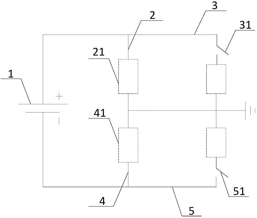
[0070] figure 1 A possible structural schematic diagram of the insulation resistance detection circuit provided by the embodiment of the present invention, as shown in figure 1 As shown, the insulation resistance detection circuit provided by the embodiment of the present invention may include: a battery 1 , a first branch 2 , a second branch 3 , a third branch 4 , and a fourth branch 5 .

[0071] Such as figure 1 As shown, the positive pole of the battery 1 is connected to the first end of the first branch 2 , and the first end of the second branch 3 is connected to the first end of the first branch 2 . Wherein, the first branch 2 is provided with a first voltage output point 21, the second branch 3 is provided with a first switch 31, and the second end of the first branch 2 and the second end of the second branch 3 Both are grounded.

[0072] Such as figure 1 As shown, the negative pole of the battery 1 is connected to the first end of the third branch 4 , and the first en...

Embodiment 2

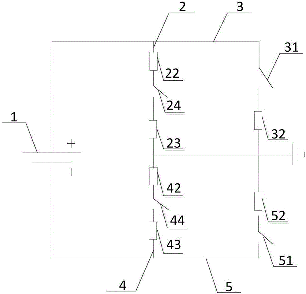
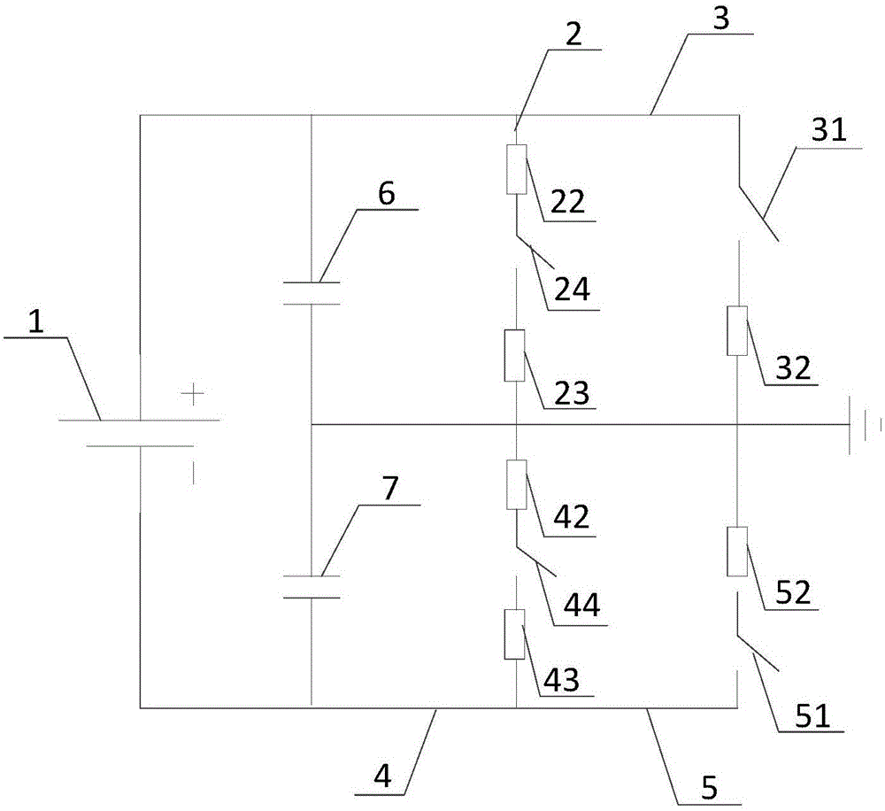
[0087] combine Figure 1 ~ Figure 3 As shown in the structure and the foregoing related descriptions, the embodiment of the present invention also provides a method for detecting insulation resistance, such as Figure 4 As shown, this figure is a flow chart of the second embodiment of the insulation resistance detection method provided by the embodiment of the present invention. The insulation resistance detection method provided by the embodiment of the present invention may specifically include the following steps:

[0088] 201. Collect the first voltage at the first voltage output point and the first voltage at the second voltage output point respectively.

[0089] In the embodiment of the present invention, it is set that the first branch includes the first resistor and the second resistor, the second branch includes the first fixed value resistor, the third circuit includes the third resistor and the fourth resistor, and the fourth A second fixed-value resistor is includ...


PUM


Abstract

The embodiment of the invention provides an insulation resistance detection circuit and method. The insulation resistance detection circuit provided by the embodiment of the invention comprises a battery, a first branch, a second branch, a third branch and a fourth branch, wherein the anode of the battery is connected with the first end of the first branch, a first voltage output point is arranged in the first branch, a first switch is arranged in the second branch, the first end of the second branch is connected with the first end of the first branch, the second end of the first branch and the second end of the second branch are both grounded, the cathode of the battery is connected with the first end of the third branch, a second voltage output point is arranged in the third branch, a second switch is arranged in the fourth branch, the first end of the fourth branch is connected with the first end of the third branch, and the second end of the third branch and the second end of the fourth branch are both grounded. According to the technical scheme, the detection range of the insulation resistance is expanded, and the detection efficiency of the insulation resistance is improved.

Description

technical field [0001] The invention relates to the field of circuit technology, in particular to an insulation resistance detection circuit and method. Background technique [0002] In an electric vehicle that uses electric energy as power, the system that powers the electric vehicle consists of a battery and a battery management system, among which the battery management system controls the operation of the battery. During the use of the battery car, changes in the environment inside the car, changes in the external climate, aging lines, etc., will directly lead to insulation failures. [0003] After an insulation fault occurs, the function of the system will run incorrectly, such as an error signal in the signaling device, misoperation of the relay device, etc. Due to the high voltage of the battery, it will also pose a threat to the life safety of users in the car when it is serious. Therefore, an insulation resistance detection circuit is designed in the system, and t...

Claims


Application Information

Patent Timeline
IPC IPC(8): G01R27/02
CPCG01R27/025
Inventor 乔宏冰贾慧华炎杰
Owner 컨템포러리엠퍼렉스테크놀로지씨오리미티드
Why Eureka
Try Eureka