Power Adapter Test Circuit
A power adapter and test circuit technology, applied in the direction of instruments, measuring electricity, measuring devices, etc., can solve the problems of increased operation cost, long operation time, inaccurate detection, etc., so as to reduce the production cost, shorten the operation time, avoid burn effect
- Summary
- Abstract
- Description
- Claims
- Application Information
AI Technical Summary
Problems solved by technology
Method used
Image

Examples
Embodiment Construction
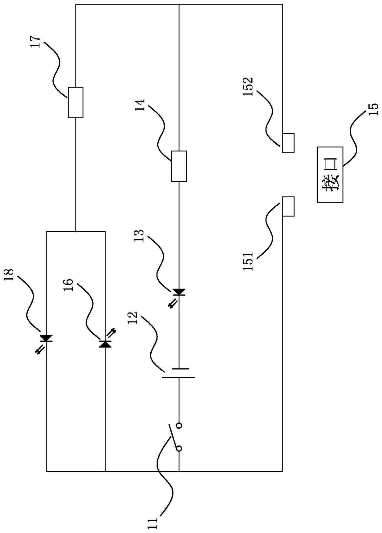
[0022] see figure 1 , which is a circuit diagram of a preferred embodiment of the power adapter test circuit of the present invention.
[0023] In order to achieve the above object, the present invention provides a power adapter test circuit for detecting the welding status of the power adapter, one end of the power adapter is selectively connected to an external power supply 19, and the other end has a positive pin and a Negative pin, including:
[0024] Switch 11, which is used to control the connection and disconnection of the test circuit;
[0025] A battery 12, the positive pole of which is connected to one end of the switch 11;
[0026] The first light-emitting diode 13, the negative pole of which is connected to the negative pole of the battery 12;
[0027] A first resistor 14, one end of which is connected to the anode of the first light emitting diode 13;
[0028] The interface 15 has a first terminal 151 and a second terminal 152, the first terminal 151 is connec...
PUM
 Abstract
Description
Claims
Application Information