High-voltage switch cabinet fault monitoring device

A high-voltage switchgear, fault monitoring technology, applied in the direction of measuring devices, measuring electricity, measuring electrical variables, etc., can solve problems such as immature development, sound wave distortion, and high price

Active Publication Date: 2017-01-04
INST OF ELECTRICAL ENG CHINESE ACAD OF SCI
View PDF6 Cites 6 Cited by
  • Summary
  • Abstract
  • Description
  • Claims
  • Application Information

AI Technical Summary

Problems solved by technology

Due to the complex internal structure of the switchgear, the sound waves of the ultrasonic method are attenuated and severely distorted during the propagation process, and the anti-interference performance is not good; for example, the signal detected by the UHF method will be refracted and reflected multiple times inside the switchgear with a complex structure. etc., will cause great attenuation and distortion of the received signal, and the price is expensive, and the development is not yet mature; the pulse current method is susceptible to interference and leads to misjudgment when used on site, and the detection results of transient-to-ground voltage are unreliable
In addition, multiple switchgears are usually used side by side, which leads to serious mutual interference of electromagnetic signals of partial discharge, and it is difficult to realize electrical detection and ultrasonic detection.
Based on the current research results, it can be seen that some single methods cannot meet the needs of switchgear detection

Method used


Image

  • High-voltage switch cabinet fault monitoring device
  • High-voltage switch cabinet fault monitoring device

Examples


Embodiment Construction

[0027] The present invention will be further described below in conjunction with the accompanying drawings and specific embodiments.

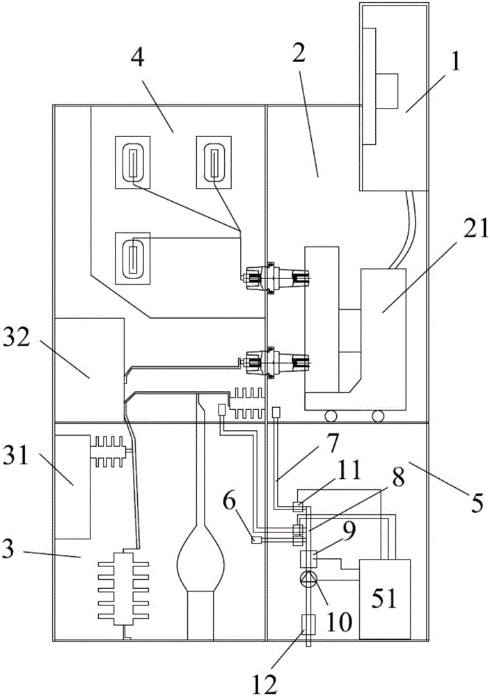
[0028] figure 1 It is a schematic diagram of Embodiment 1 of the fault monitoring device of the present invention. like figure 1 As shown, the high-voltage switchgear includes 5 high-voltage compartments including relay instrument room 1, handcart room 2, cable room 3, busbar room 4 and tool room 5. There is a circuit breaker handcart 21 in the handcart room 2 , a grounding switch device 31 is installed in the cable room 3 , and a current transformer 32 is installed in the busbar room 4 .

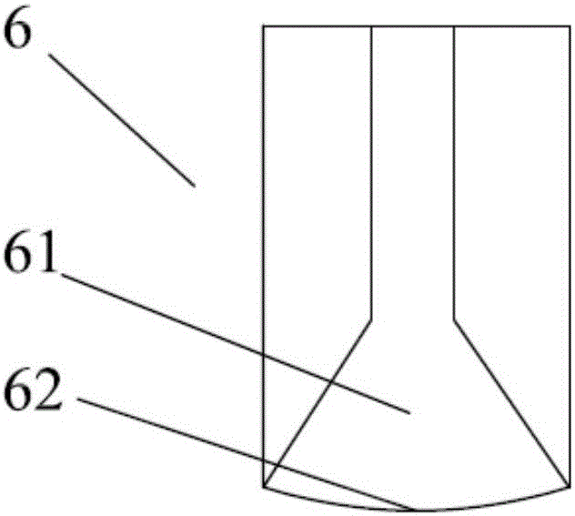
[0029] The fault monitoring device of the present invention includes: a gas probe 6 , a gas pipeline 7 , an air outlet pipe 8 , a gas detector 9 , a normally closed solenoid valve 11 , an air pump 10 , an exhaust gas filter 12 and an information processing module 51 .

[0030] Multiple gas probes 6 can be installed, and three are installed in this embodim...


PUM


Abstract

The invention discloses a high-voltage switch cabinet fault monitoring device, which comprises gas probes (6), gas pipelines (7), a gas detector (9), a gas pump (10), an outlet pipe (8), a normally-closed solenoid valve (11), a waste gas filter (12) and an information processing module (51). Through detecting gases generated by discharging, fault of the high-voltage switch cabinet is monitored, and thus, electrified monitoring and continuous monitoring on hidden fault inside the switch cabinet can be realized. Through the gas probe with a horn-type opening structure arranged in each compartment inside the high-voltage switch cabinet, the gases are detected and decomposed, the gas detector (9) is adopted to measure the contents of components of each gas, and according to information such as discharged decomposed gas type and the concentrations obtained through detection by gas probes (6) arranged at different positions, the information processing module (51) judges hidden fault. The gas pipelines (7) are arranged along the insulated separators and the inner wall of the high-voltage switch cabinet. The gas probes (6) and the gas pipelines (7) are made of insulated material, preferably, polytetrafluoroethylene material.

Description

technical field [0001] The invention relates to a monitoring device for a high-voltage switchgear, in particular to a fault monitoring device based on gas detection. Background technique [0002] As a large amount of equipment used in the power grid, the high-voltage switchgear is directly related to the user's power supply. If it breaks down and causes an accident, the economic loss and social loss will be very large. In addition, due to the narrow space inside the switchgear, many parts, complex structure, and small insulation distance, insulation defects are more likely to occur than other equipment, which brings huge hidden dangers to the safe operation of the equipment. Therefore, monitoring the partial discharge, overheating and other faults of the high-voltage switchgear in operation can provide important parameters and basis for the condition maintenance of the switchgear, improve the efficiency of the test and maintenance of the switchgear, thereby avoiding sudden a...

Claims


Application Information

Patent Timeline
Patent Type & Authority Applications(China)
IPC IPC(8): G01R31/12G01N33/00
CPCG01N33/0037G01N33/004G01R31/1254
Inventor 李康张国强
Owner INST OF ELECTRICAL ENG CHINESE ACAD OF SCI
Why Eureka
Try Eureka