Servo motor endurance test device and test method thereof

A servo motor and testing device technology, applied in the direction of motor generator testing, etc., can solve the problems that the tested product cannot be operated under high load, the durability effect of the servo motor is not obvious, and the durability cannot be tested at the same time, so as to achieve enhanced durability testing effect, the accuracy of durability test results, and the effect of improving durability test efficiency

Inactive Publication Date: 2017-01-04
XIAOGAN HUAGONG GAOLI ELECTRONICS
View PDF8 Cites 4 Cited by
  • Summary
  • Abstract
  • Description
  • Claims
  • Application Information

AI Technical Summary

Problems solved by technology

[0004] 1. In the case of no-load, the durability effect of the servo motor is not obvious, and the high-load operation of the tested product cannot be achieved. It takes a long time to perform the durability test, the production test cycle is long, a large amount of electric energy is wasted, and the test efficiency is low;
[0005] 2. In the case of loading, although the servo motor has a load, because the load is a fixed value, it is always in the same working state, or continues in some working states with little change, so it cannot be tested at the same time. The durability problem in this working condition, the pass rate of the durability test is high, the accuracy is low, and some faulty machines cannot be tested

Method used


Image

  • Servo motor endurance test device and test method thereof
  • Servo motor endurance test device and test method thereof
  • Servo motor endurance test device and test method thereof

Examples


Embodiment 1

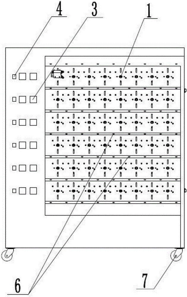
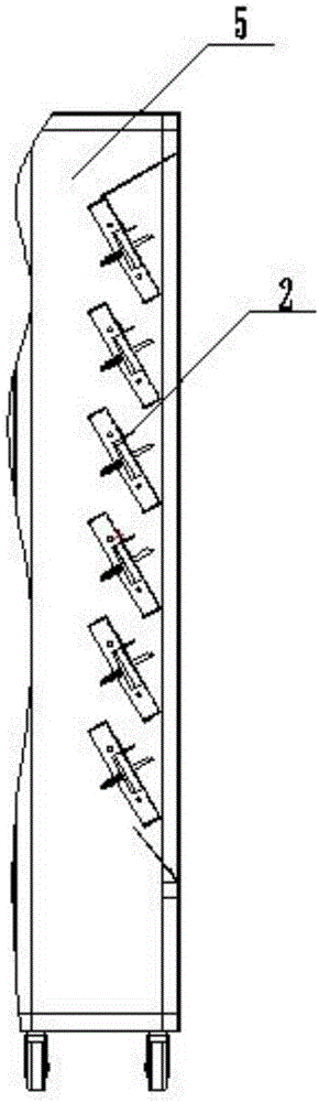
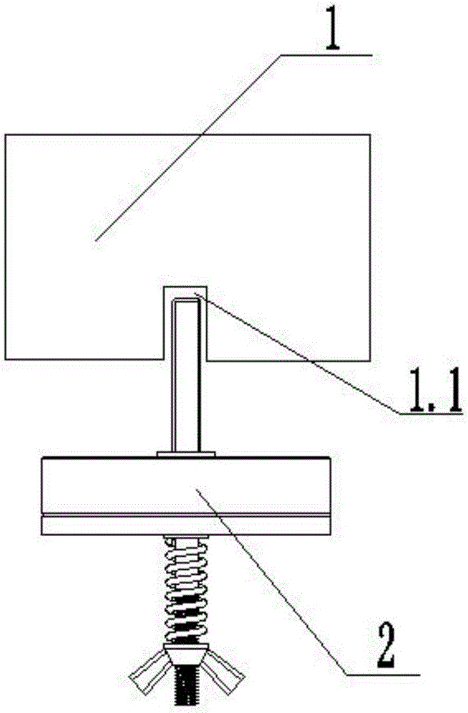
[0033] Such as Figure 1~4 As shown, a servo motor durability test device includes a servo motor 1, a mechanical load assembly 2 for providing the load required by the servo motor 1, and a power supply device 4. The output shaft 2.1 of the mechanical load assembly 2 and the servo The input hole 1.1 of the motor 1 is connected, and the power supply device 3 is electrically connected with the plug of the servo motor 1. The output shaft 2.1 of the mechanical load assembly 2 is sequentially installed with rolling bearing 2.2, bearing seat 2.3, friction plate 2.4, spring 2.6 and adjusting nut 2.7. The friction plate 2.4 and bearing seat 2.3 can be adjusted by adjusting the adjusting nut 2.7. The friction between the two, so as to control the output load of the output shaft 2.1 on the mechanical load assembly 2. To test the durability of the servo motor 1 under different load conditions, only need to adjust the friction between the friction plate 2.4 and the bearing seat 2.3 to outp...

Embodiment 2

[0037] Such as Figure 1~4 As shown, the present invention provides a servo motor durability test device, including a servo motor 1, a mechanical load assembly 2 for providing the load required by the servo motor 1, and a power supply device 4, the output shaft of the mechanical load assembly 2 2.1 is connected to the input hole 1.1 of the servo motor 1, and the power supply device 3 is electrically connected to the plug of the servo motor 1. The output shaft 2.1 of the mechanical load assembly 2 is sequentially installed with rolling bearing 2.2, bearing seat 2.3, friction plate 2.4, spring 2.6 and adjusting nut 2.7. The friction plate 2.4 and bearing seat 2.3 can be adjusted by adjusting the adjusting nut 2.7. The frictional force between the two, so as to adjust the output load of the output shaft 2.1 of the mechanical load assembly 2.

[0038] The difference between the second embodiment and the first embodiment is that the second embodiment also includes a time relay 3, whi...


PUM


Abstract

The invention discloses a servo motor endurance test device and a test method thereof. The servo motor endurance test device comprises a servo motor, a mechanical load assembly which is used for providing load required by the servo motor and a power supply device. The output shaft of the mechanical load assembly is connected with the input port of the servo motor. The power supply device is electrically connected with the plug of the servo motor. According to the device and the test method thereof, the test period is short, rapid endurance of equipment can be realized, the range is application is wide and the yield rate of the product market can be enhanced.

Description

Technical field [0001] The invention relates to the field of servo motor durability testing, in particular to a servo motor durability testing device and a testing method thereof. Background technique [0002] With the development of society, people have higher and higher requirements for the quality of servo motors. In order to improve the yield of servo motors and avoid product failures in the early stages of use, it is necessary to carry out durability tests on the servo motors before leaving the factory. The so-called endurance test is to allow the equipment to operate in an ultra-conventional special environment, or to allow the equipment to run beyond the specifications; so that the defects of the product can be revealed in a short period of time, so as to prevent the product from being in the hands of the user. It fails. When testing the durability of the servo motor, it is necessary to place the servo motor in a certain working environment; then continue to run for a per...

Claims


Application Information

Patent Timeline
Patent Type & Authority Applications(China)
IPC IPC(8): G01R31/34
CPCG01R31/34
Inventor 刘鑫
Owner XIAOGAN HUAGONG GAOLI ELECTRONICS
Why Eureka
Try Eureka