Supercharge Your Innovation With Domain-Expert AI Agents!

Magnetic resonance imaging system and its parameter determining method

A technology of magnetic resonance imaging and imaging space, which is applied in the direction of using nuclear magnetic resonance imaging system for measurement, magnetic resonance measurement, measurement of magnetic variables, etc., which can solve the problems of high cost and occupation of subject space.

Pending Publication Date: 2017-01-04
SUZHOU INST OF BIOMEDICAL ENG & TECH CHINESE ACADEMY OF SCI
View PDF9 Cites 9 Cited by
  • Summary
  • Abstract
  • Description
  • Claims
  • Application Information

AI Technical Summary

Problems solved by technology

[0007] The technical problem to be solved by the present invention is to overcome the defect that the eddy current elimination device in the prior art needs to occupy additional space that can be used by the subjects and has high cost

Method used


Image

  • Magnetic resonance imaging system and its parameter determining method
  • Magnetic resonance imaging system and its parameter determining method
  • Magnetic resonance imaging system and its parameter determining method

Examples


Embodiment 1

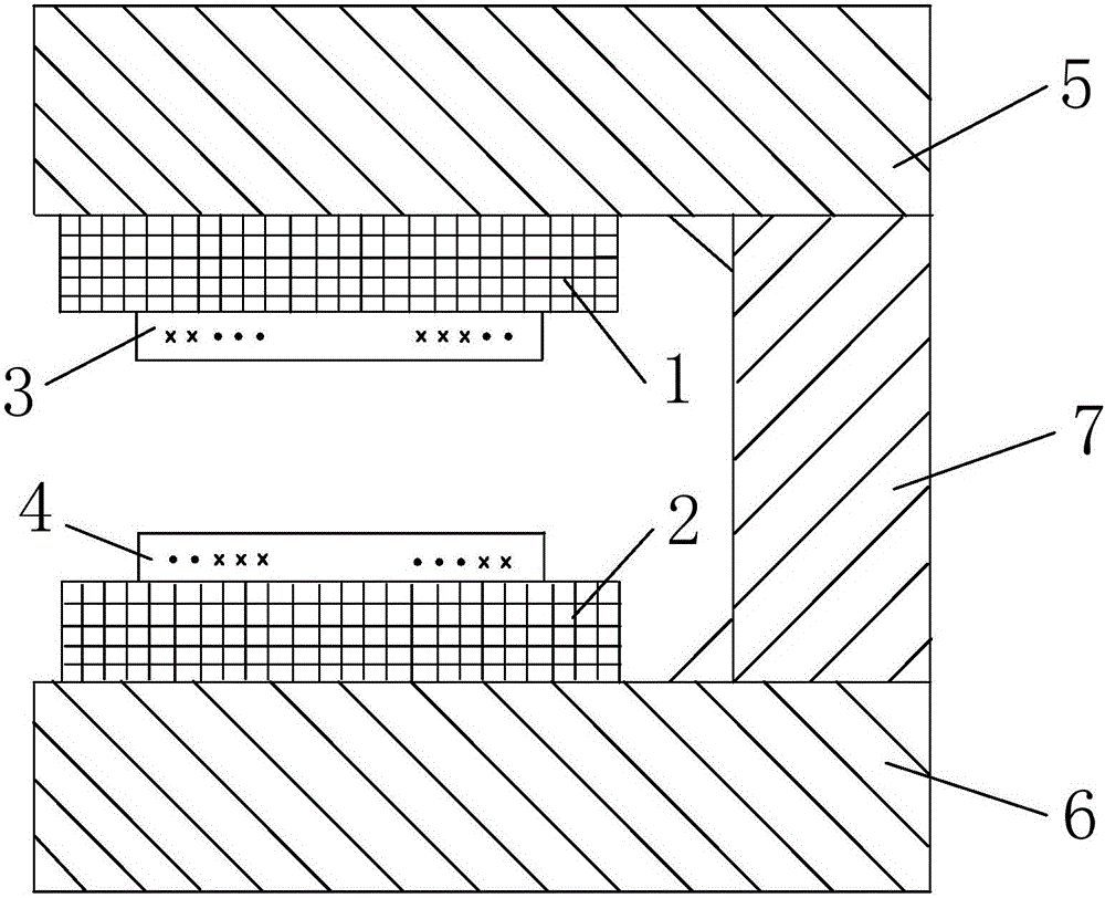
[0025] This embodiment provides a magnetic resonance imaging system, such as Figure 1A shown. The magnetic resonance imaging system includes an upper magnet 1 , a lower magnet 2 , an upper shim ring 3 and a lower shim ring 4 .

[0026] The upper magnet 1 and the lower magnet 2 are arranged facing each other, so that there is a uniform main magnetic field in the imaging space.

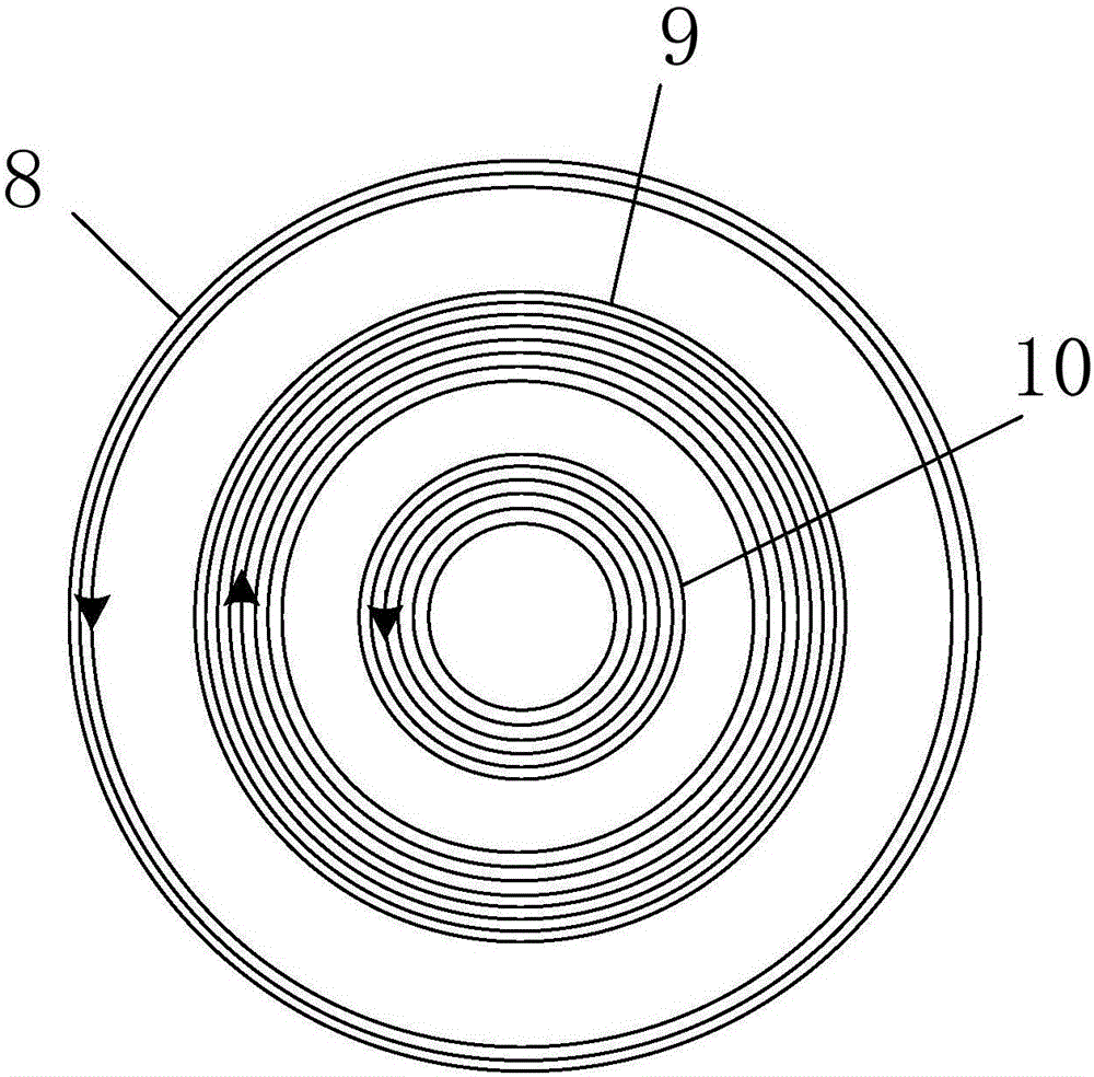
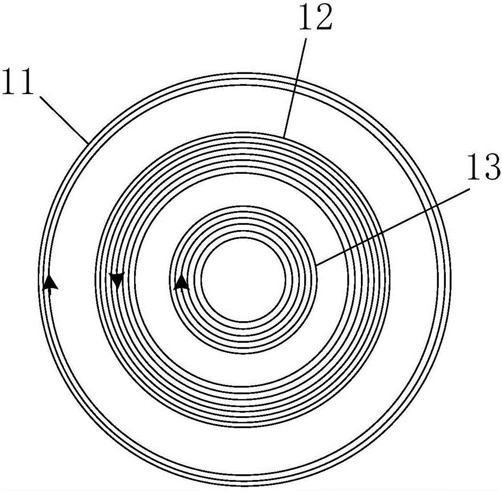
[0027] The upper shim ring 3 is arranged under the upper magnet 1 . The upper shim ring 3 is provided with a first gradient coil and a first active shielding coil. The first active shielding coil is arranged on the outer periphery of the first gradient coil, such as Figure 1A As shown in , in the upper shim ring 3, "×" indicates the direction of current flowing from the front of the paper or screen to the inside of the paper or screen, and "·" indicates the direction of current flowing from the inside of the paper or screen to the front of the paper or screen. "Front" here refers to the direction in...

Embodiment 2

[0038] This embodiment provides a method for determining the parameters of the magnetic resonance imaging system described in Embodiment 1, such as figure 2 shown, including the following steps:

[0039] Step S10: Establish a magnetic field distribution model in the imaging space; the magnetic field in the imaging space includes the gradient magnetic field generated by the first gradient coil and the second gradient coil, the eddy current magnetic field generated when the gradient magnetic field acts on the metal substance, the first active shielding coil and the second gradient coil. The suppression magnetic field generated by the two active shielding coils.

[0040] Step S20: Carry out dynamic optimization simulation on the imaging spatial magnetic field distribution model, and determine the range of turns and the range of diameters of the first active shielding coil and the second active shielding coil when the ratio of the eddy current magnetic field to the gradient magne...


PUM


Abstract

The invention discloses a magnetic resonance imaging system and its parameter determining method wherein the magnetic resonance imaging system comprises an upper magnet, a lower magnet, an upper grading ring and a lower grading ring. The upper magnet and the lower magnet are arranged in opposite. The upper grading ring is provided therein with a first gradient coil and a first active shield coil. The first active shield coil is arranged around the exterior circumference of the first gradient coil. The current flow direction of the first active shield coil is opposite to that of the first gradient coil. The lower grading ring is provided therein with a second gradient coil and a second active shield coil. The second active shield coil is arranged around the exterior circumference of the second gradient coil. The current flow direction of the second active shield coil is opposite to that of the second gradient coil. The current flow direction of the second active shield coil is opposite to that of the first active shield coil. According to the invention, the magnetic fields generated from active shield coils are utilized to suppress an eddy-current magnetic field. As the active shield coils are arranged around the exterior circumferences of the gradient coils, they do not occupy more internal caliber space of the magnets.

Description

technical field [0001] The invention relates to the field of magnetic resonance imaging, in particular to a magnetic resonance imaging system and a parameter determination method thereof. Background technique [0002] In 1946, Felix Bloch of Stanford University and Edward Purcell of Harvard University detected the magnetic resonance absorption phenomenon in the inner core of matter through their independent research, and explained the existence of nuclear spin. Based on this physical principle, nuclear magnetic resonance is widely used in physical chemistry. archaeology and medical fields. Now, nuclear magnetic resonance equipment (MRI) developed based on the principle of nuclear spin has become the most important medical imaging equipment alongside CT, ultrasound and other imaging equipment, and is widely used in imaging diagnosis of various parts of the human body. [0003] The gradient coil is one of the core components of the magnetic resonance equipment, and its main f...

Claims


Application Information

Patent Timeline
IPC IPC(8): G01R33/48G01R33/385A61B5/055
CPCA61B5/055G01R33/385G01R33/48
Inventor 徐雅洁常严陈巧燕杨晓冬
Owner SUZHOU INST OF BIOMEDICAL ENG & TECH CHINESE ACADEMY OF SCI
Features
  • R&D
  • Intellectual Property
  • Life Sciences
  • Materials
  • Tech Scout
  • Unparalleled Data Quality
  • Higher Quality Content
  • 60% Fewer Hallucinations
Learn More