Global Navigation Satellite System (gnss) Spoofing Detection With Carrier Phase And Inertial Sensors

A global navigation satellite and carrier phase technology, applied in satellite radio beacon positioning systems, radio wave measurement systems, instruments, etc., can solve problems such as not an ideal solution, increased installation costs, etc.

Active Publication Date: 2017-01-04
HONEYWELL INT INC
View PDF19 Cites 9 Cited by
  • Summary
  • Abstract
  • Description
  • Claims
  • Application Information

AI Technical Summary

Problems solved by technology

This is not an ideal solution as it adds significant cost to the GNSS installation

Method used


Image

  • Global Navigation Satellite System (gnss) Spoofing Detection With Carrier Phase And Inertial Sensors
  • Global Navigation Satellite System (gnss) Spoofing Detection With Carrier Phase And Inertial Sensors
  • Global Navigation Satellite System (gnss) Spoofing Detection With Carrier Phase And Inertial Sensors

Examples


example 1

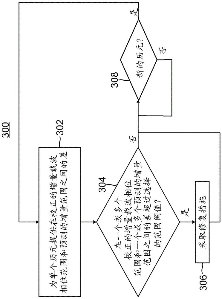
[0078] Example 1 includes a system for detecting spoofing attacks, the system comprising: a satellite motion and receiver clock correction module communicatively coupled to periodically input from a global navigation satellite system (GNSS) receiver for multiple signals in the field of view of the GNSS receiver The carrier phase range of satellites, the satellite motion and the receiver clock correction module are communicatively coupled to output a corrected delta carrier phase range for the current epoch to a first input of the subtractor; compute the predicted range and the delta range module communicatively coupled to output to a second input of the subtractor a predicted delta range based on the inertial measurements observed for the current epoch; the subtracter to output to the delta range difference detection logic for the current epoch the difference between the corrected delta carrier phase range and the predicted delta range for the epoch; and delta range difference ...

example 2

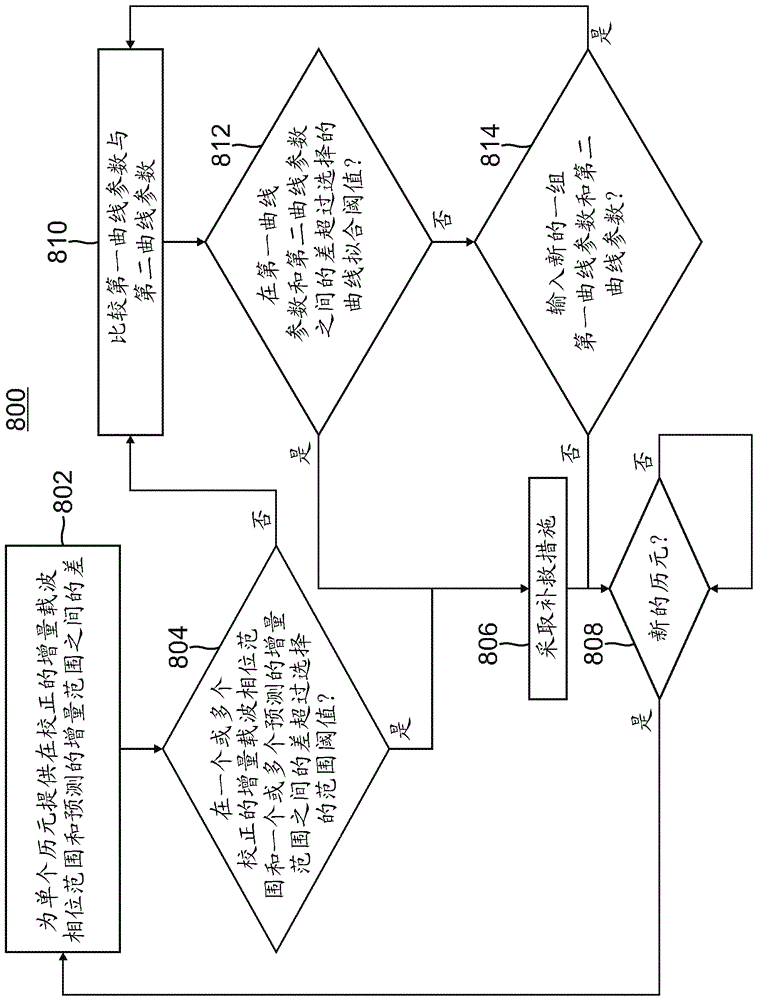
[0079] Example 2 includes the system of Example 1, further comprising: a first curve fitting module configured to: input from the satellite motion and receiver clock correction module the plurality of corrected carrier phase ranges obtained continuously during the respective plurality of epochs ; fitting a plurality of corrected carrier-phase ranges obtained in succession to a first curve in an appropriate order of selection; and outputting information indicating first curve parameters associated with the first curve to the curve fit detection logic; the second curve a fitting module configured to: input a plurality of predicted ranges obtained continuously during respective plurality of epochs from the calculate predicted range and incremental range module; fit the continuously obtained plurality of predicted ranges to the selected a second curve in an appropriate order; and outputting to the curve-fit detection logic information indicative of a second curve parameter associat...

example 3

[0080] Example 3 includes the system of Example 2, further comprising: a processor configured to execute at the satellite motion and receiver clock correction module, the calculate predicted range and delta range module, the first curve fitting module, and the second first curve fitting module. An algorithm in the Curve Fitting module.


PUM


Abstract

The application relates to global navigation satellite system (gnss) spoofing detection with carrier phase and inertial sensors. A system to detect spoofing attacks is provided. The system includes a satellite-motion-and-receiver-clock-correction module, a compute-predicted-range-and-delta-range module, a subtractor, and delta-range-difference-detection logic. The satellite-motion-and-receiver-clock-correction module outputs a corrected-delta-carrier-phase range for a current epoch to a first input of a subtractor. The compute-predicted-range-and-delta-range module outputs a predicted delta range to a second input of the subtractor. The predicted delta range is based on inertial measurements observed for the current epoch. The subtractor outputs a difference between the corrected-delta-carrier-phase range and the predicted delta range for the current epoch to delta-range-difference-detection logic. The delta-range-difference-detection logic determines that, if the difference exceeds a selected-range threshold, the GNSS receiver was spoofed in the current epoch.

Description

Background technique [0001] Global Navigation Satellite System (GNSS) is a satellite system used to find out the geographic location of GNSS receivers. Spoofing of GNSS systems is typically used to cause erroneous navigation data to be output from a navigation system in a vehicle using the GNSS satellite system. Figure 2A An exemplary GNSS spoofing attack on an unprotected vehicle 51 is shown. like Figure 2A As shown in , the spoofing system includes an antenna 306 that inputs satellite signals from a plurality of respective satellites 351 , 352 and 353 in view of the vehicle 51 via wireless data links 321 , 322 and 323 . Satellite signals received at antenna 306 are modified by spoofer electronics and logic 305 . The spoofing system also includes an antenna 307 that transmits the modified satellite signal to a navigation system on the vehicle 51 via a wireless data link 315 . The modified satellite signals received at the GNSS receiver of the unprotected vehicle 51 via th...

Claims


Application Information

Patent Timeline
IPC IPC(8): G01S19/01G01S19/21
CPCG01S19/015G01S19/21G01S19/215G01S19/246G01S19/29
Inventor B.W.施珀K.斯维尼W.J.豪金森
Owner HONEYWELL INT INC
Why Eureka
Try Eureka