
Data collection device

A data collection and data technology, applied in data processing applications, signal transmission systems, transmission systems, etc., can solve the problems of inconvenient diversion of nuclear power units, no sharing, system equipment costs, and high costs of design and installation, and achieve Realize the effect of real-time automatic analysis and processing and result presentation, saving labor costs, and real-time early warning of abnormal working conditions

Pending Publication Date: 2017-01-04
CENT RES INST OF BUILDING & CONSTR CO LTD MCC GRP +1
View PDF11 Cites 2 Cited by
  • Summary
  • Abstract
  • Description
  • Claims
  • Application Information

AI Technical Summary

Problems solved by technology

[0013] (3) The plumb line is manually measured, read and recorded at the 4 points of the cylinder through the manual running point, which involves some equipment located in the K area, which has a certain radiation risk;
[0014] (4) The prestress gauges are manually measured, read and recorded at 4 points in the corridor through manual running points, and need to go up and down repeatedly through the ladder, which has certain industrial safety hazards
However, the above-mentioned devices also have the disadvantages of low economy and no sharing. For example, each unit needs to be configured independently, the equipment cost of the system and the cost of design and installation investment are high, the system is highly specific, and it is not easy to divert it to other equipment. Similar nuclear power units; at the same time, because it is customized and fixed, the system device is not portable, and the use objects are often limited to the owner's needs for long-term operation

Method used


Image

  • Data collection device
  • Data collection device
  • Data collection device

Examples


Embodiment Construction

[0052] In order to make the technical solutions and advantages of the present invention clearer, the present invention will be further described in detail below in conjunction with the accompanying drawings and specific embodiments.

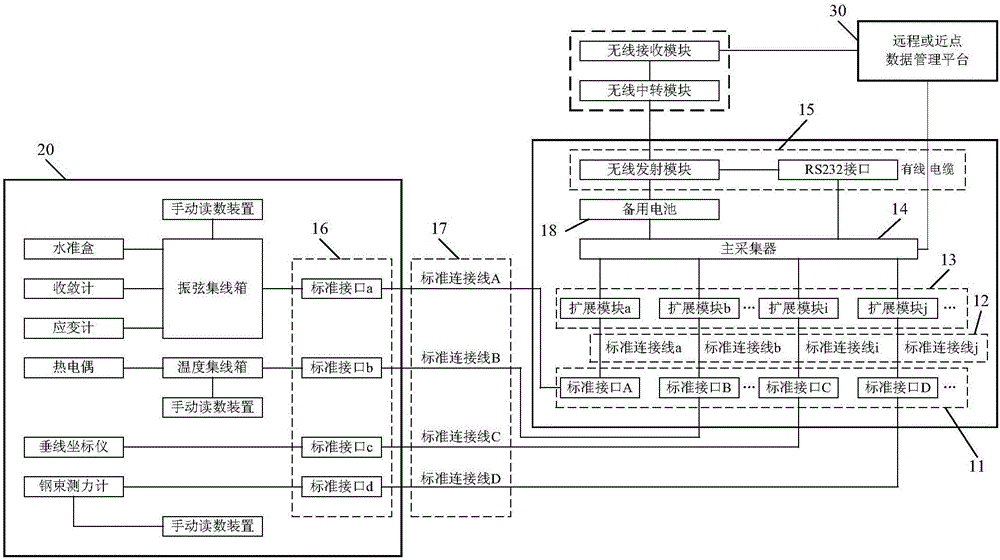
[0053] figure 1 It is a schematic structural diagram of the data collection device in the embodiment of the present invention. Such as figure 1 As shown, the data collection device in the embodiment of the present invention includes: a first standard interface group 11, a first standard connection line group 12, an expansion module group 13, a main collector 14 and a data output module 15;

[0054] The first standard interface group 11 includes: a plurality of standard interfaces; for example, as figure 1 As shown, the first standard interface group 11 may include: standard interfaces A, B, C, D and other standard interfaces;

[0055] The first standard connecting wire group 12 includes: a plurality of various types of standard connecting wire...


PUM


Abstract

The invention provides a data collection device. The data collection device comprises a first standard interface group, a first standard connection line group, an extended module group, a main collector and a data output module, wherein each standard interface in the first standard interface group is used for receiving measured data output by a line collection box or a sensor, and transmitting the received measured data to a corresponding extended module; each extended module in the extended module group is used for transmitting the received measured data to the main collector; and the main collector is used for outputting the received measured data through the data output module. By adopting the data collection device, the measured data in each sensor of each set can be automatically read and collected; the data collection device is convenient to carry and mount / detach, so that the utilization efficiency is improved and a lot of manual cost is saved; and the device has high reusability and good economical efficiency, can be used for reading and collecting data of different nuclear power units and can also realize real-time automatic analysis processing and result presentation.

Description

technical field [0001] The invention relates to the technical field of safety monitoring, in particular to a data collection device. Background technique [0002] With the vigorous development of nuclear power in China, there are more than 50 nuclear power plant units under construction and in service, among which M310 pressurized water reactors (Daya Bay No. 1 / 2, Ling Ao Phase I No. Water reactor CPR1000 (No. 3 / 4 of Ling'ao Phase II, No. 1-6 of Hongyanhe, No. 1-4 of Ningde, No. 1-6 of Yangjiang, No. 1 / 2 of Fangchenggang) or M310+ (Phase I expansion of Qinshan, Fuqing 1-6 No. 4) pile type is dominant (large quantity). As the third and last safety barrier of these nuclear power plants, the containment structure of the nuclear reactor enclosure has basically the same, a large number of permanent civil inspection instruments buried in it, the purpose of which is to test the mechanical properties of the containment structure of the nuclear power plant . [0003] According to ...

Claims


Application Information

Patent Timeline
IPC IPC(8): G08C17/02G08C19/00H04L29/08G06Q50/06G21C17/10G21C17/112G21C17/12
CPCH04L67/12G06Q50/06G08C17/02G08C19/00G21C17/10G21C17/112G21C17/12Y02E30/30
Inventor 张忠王雷张大勇岳红波万俊闻程敦旵姜皓梁斌韩正田科浪常维汪洋姚辉
Owner CENT RES INST OF BUILDING & CONSTR CO LTD MCC GRP
Learn More