Method for reducing display unevenness of liquid crystal display panel

A liquid crystal display panel and uneven display technology, which is applied to static indicators, instruments, etc., can solve the problems of uneven display of liquid crystal display panels, affect the quality of picture display, and small delay, so as to avoid uneven display and improve display. Effect, effect of delay difference reduction

Inactive Publication Date: 2017-01-04
WUHAN CHINA STAR OPTOELECTRONICS TECH CO LTD
View PDF5 Cites 6 Cited by
  • Summary
  • Abstract
  • Description
  • Claims
  • Application Information

AI Technical Summary

Problems solved by technology

[0006] In view of the above prior art, an RC circuit is usually used in the demultiplexing circuit of the liquid crystal display panel to protect the switching tube from overcurrent. However, due to the time delay of the RC circuit, the input at both ends of the demultiplexing signal circuit , passing through multiple switch tubes at the same time through multiple RC circuits, resulting in the increase of the passing RC circuits, when the number of passing RC circuits reaches a certain number, the demultiplexing signal is accumulated by delay, and the demultiplexing The signal output by the circuit has different degrees of delay, which causes the demultiplexing signal input at both ends of the demultiplexing circuit to pass through less RC circuits, resulting in a small delay, and the demultiplexing signal is transmitted to the demultiplexing circuit. When the middle part of the multiplexing circuit passes through the multi-stage RC circuit, there is a serious delay difference between the output signal and the output signal at both ends of the demultiplexing circuit, resulting in uneven display of the liquid crystal display panel, thus Defects that affect the display quality of the picture, the present invention proposes a method for reducing the display unevenness of the liquid crystal display panel

Method used


Image

  • Method for reducing display unevenness of liquid crystal display panel
  • Method for reducing display unevenness of liquid crystal display panel
  • Method for reducing display unevenness of liquid crystal display panel

Examples


Embodiment 1

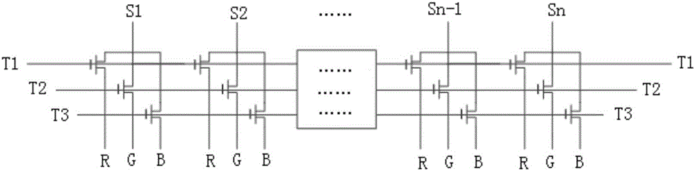
[0035] image 3 In embodiment 1, in the demultiplexing circuit, a group of buffers is connected in series between each adjacent two-stage circuit, and a group of buffers is connected in series between each adjacent two-stage circuits . Each stage of circuit includes one or more groups of driving circuits for driving R sub-pixels, G sub-pixels and B sub-pixels respectively. Each group of driving circuits includes three switch tubes respectively used to drive R sub-pixels, G sub-pixels and B sub-pixels, and both ends of each switch tube are connected in parallel with RC circuits. Each group of buffers includes three buffers, and the demultiplexing signal input end of the switching transistor of each sub-pixel is connected in series with one buffer.

[0036] The buffer will correct the delay generated by each stage of the circuit, reducing the delay caused by the RC to the delay difference between the left and right sides of the circuit and the intermediate output signal.

[0...

Embodiment 2

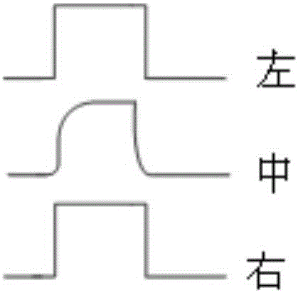
[0040] Figure 5 In Example 2, two sets of inverters are connected in parallel on the front-stage circuit in the signal transmission direction of the demultiplexing circuit, that is, in the Figure 5 The circuits on the left and right sides of the center are respectively connected in parallel with two sets of inverters; in this type, the input signal terminals on the left and right sides of the demultiplexing circuit lead out signal lines to connect to the two-stage inverters, and the output signals are connected to the circuits in the middle area. Therefore, the delay caused by the RC in the output signal in the middle area of ​​the demultiplexing circuit is reduced, so that the delay difference of the output signal after being driven by the demultiplexing circuit is reduced.

[0041] Depend on Figure 5 It can be seen that the circuits on the left and right sides of the demultiplexing circuit (that is, the circuits located in the front stage of the demultiplexing signal tra...

Embodiment 3

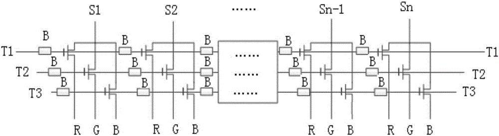
[0044] Figure 7 In Example 3, the method of adding lead wires is adopted, without changing the overall structure of the demultiplexing circuit, only the input signal terminals at the left and right ends of the demultiplexing circuit lead out signal lines and are directly connected to the demultiplexing circuit The intermediate circuit (because the demultiplexing signal is transmitted from both ends of the demultiplexing circuit to the middle of the demultiplexing circuit, so the front stage in the signal transmission direction is the left area and the right area, and the demultiplexing signal transmission direction in the rear stage is the middle area), thereby reducing the delay caused by the RC of the output signal of the intermediate circuit in the demultiplexing circuit, thereby reducing the delay difference between the output signals. The problem of uneven display of the display panel is avoided, and the display effect of the liquid crystal display panel is improved.

...


PUM


Abstract

The invention provides a method for reducing display unevenness of a liquid crystal display panel. The method comprises the following steps: dividing a multipath demultiplexing circuit into multiple levels of circuits according to the demultiplexing signal transmission direction, and using a signal compensation circuit to implement signal compensation on a circuit on the post level of the demultiplexing signal transmission direction. According to the method, the signal compensation circuit is added in the multipath demultiplexing circuit to reduce delay of a drive signal after the demultiplexing signal of the multipath demultiplexing circuit passes an RC circuit (Resistance-Capacitance network), so that the phenomenon of display unevenness of the liquid crystal display panel, caused by the signal delay difference of the RC circuit, is reduced, and the display effect of the liquid crystal display panel is improved.

Description

technical field [0001] The invention relates to the technical field of liquid crystal display, in particular to a method and system for reducing display unevenness of a crystal display panel. Background technique [0002] With the rapid development of the small and medium-sized electronic display industry, people have higher and higher requirements for the resolution quality of small and medium-sized LCD liquid crystal display screens. The improvement of the display quality is closely related to the transmission rate of the display data and the integrity of the signal. Generally, the switch tube is used to realize the drive. However, when the switch tube is used to control the switch, because the switch tube has poor overcurrent and overvoltage capabilities, it cannot work normally if reliable protection measures are not taken. Therefore, in order to control the excessive rise rate of the circuit voltage, ensure that The switching tube is safe to operate, and an RC circuit ...

Claims


Application Information

Patent Timeline
Patent Type & Authority Applications(China)
IPC IPC(8): G09G3/36
CPCG09G3/36G09G2310/0291G09G2310/0297G09G2320/0223
Inventor 马亮
Owner WUHAN CHINA STAR OPTOELECTRONICS TECH CO LTD
Why Eureka
Try Eureka