Electronic device and multi-feed antenna
An electronic device, multi-feed technology, applied in the direction of electrical short antenna, antenna, antenna components, etc., can solve the problems of antenna occupation, high cost, large area, etc., and achieve the effect of reducing the number, simple structure, and reducing cost
- Summary
- Abstract
- Description
- Claims
- Application Information
AI Technical Summary
Problems solved by technology
Method used
Image

Examples
Embodiment Construction
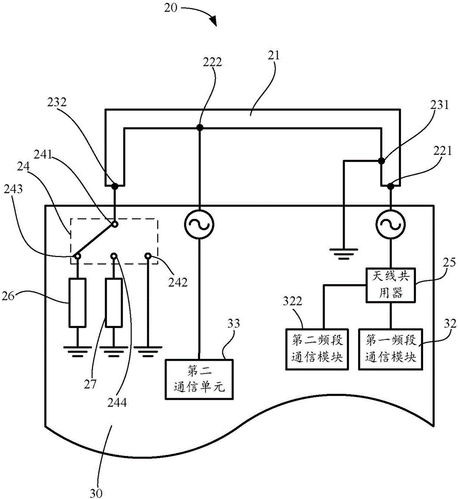
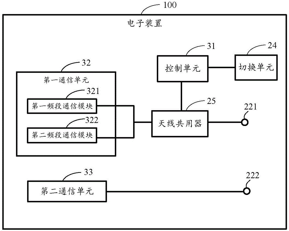
[0013] Such as figure 1 As shown, it is a schematic structural diagram of the multi-feed antenna 20 in an embodiment of the present invention. In this embodiment, the multi-feed antenna 20 is applied to an electronic device 100 (such as figure 2 shown), such as mobile phones, tablets, etc.
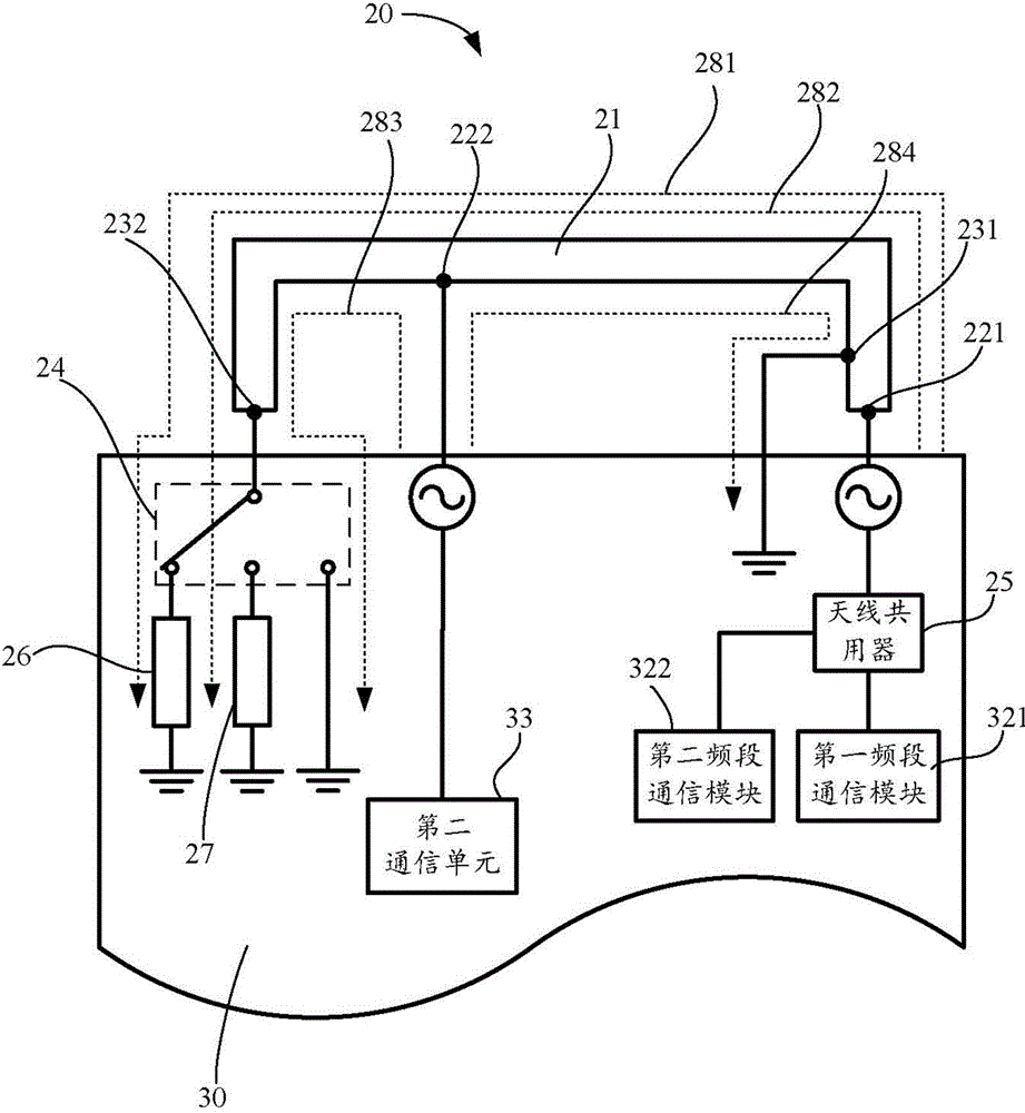
[0014] The multi-feed antenna 20 includes an antenna body 21 , several antenna feed points disposed on the antenna body 21 , and several antenna ground points disposed on the antenna body 21 . In this embodiment, the several antenna feed points at least include a first antenna feed point 221 disposed at one end of the antenna body 21 and a second antenna feed point 221 disposed between two ends of the antenna body 21. The input point 222 includes at least a first antenna ground point 231 disposed between two ends of the antenna body 21 and a second antenna ground point 232 disposed at the other end of the antenna body 21 .
[0015] In this embodiment, the plurality of antenna feeding p...
PUM
 Abstract
Description
Claims
Application Information
 - Generate Ideas
- Intellectual Property
- Life Sciences
- Materials
- Tech Scout
- Unparalleled Data Quality
- Higher Quality Content
- 60% Fewer Hallucinations
Browse by: Latest US Patents, China's latest patents, Technical Efficacy Thesaurus, Application Domain, Technology Topic, Popular Technical Reports.
© 2025 PatSnap. All rights reserved.Legal|Privacy policy|Modern Slavery Act Transparency Statement|Sitemap|About US| Contact US: help@patsnap.com