
Dual-band filtering antenna

A dual-band filter, filter antenna technology, applied in antenna coupling, waveguide type devices, radiating element structure and other directions, can solve problems such as system performance degradation

Inactive Publication Date: 2017-01-04
SHANXI UNIV
View PDF2 Cites 22 Cited by
  • Summary
  • Abstract
  • Description
  • Claims
  • Application Information

AI Technical Summary

Problems solved by technology

When the system is processing analog signals, the performance of the system is degraded due to the influence of environmental noise and electrical noise of the device

Method used


Image

  • Dual-band filtering antenna
  • Dual-band filtering antenna
  • Dual-band filtering antenna

Examples


Embodiment Construction

[0017] A dual-band filter antenna according to an embodiment of the present invention will be described in detail below with reference to the accompanying drawings.

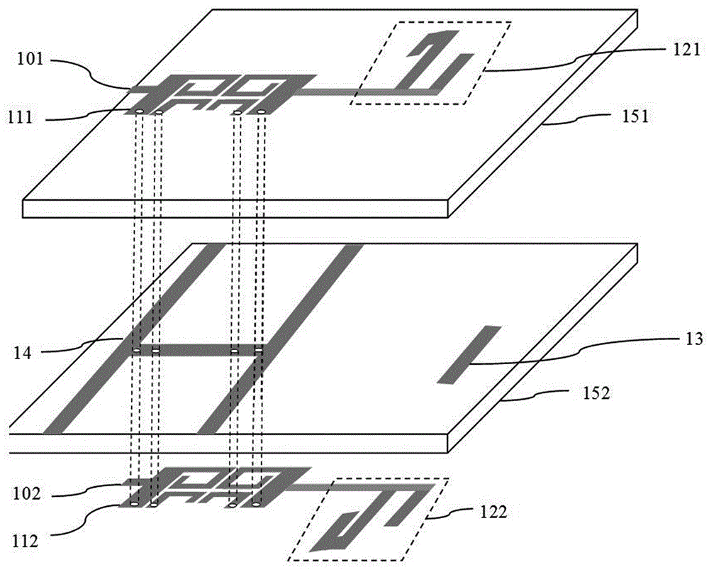
[0018] figure 1 is a schematic structural diagram of a dual-band filter antenna according to an embodiment of the present invention. Such as figure 1 As shown, the dual-band filter antenna according to the embodiment of the present invention includes a first substrate 151 and a second substrate 152 opposite to the first substrate 151 . The first radiation unit 121 , the first dual-band filter 111 and the first feeder 101 are formed on the upper surface of the first substrate 151 , and the first dual-band filter 111 is inserted into the first feeder 101 . The second radiating unit 122 , the second dual-band filter 112 and the second feeder 102 are formed on the lower surface of the second substrate 152 , and the second dual-band filter 112 is inserted into the second feeder 102 .

[0019] The first feeder 101 a...


PUM


Abstract

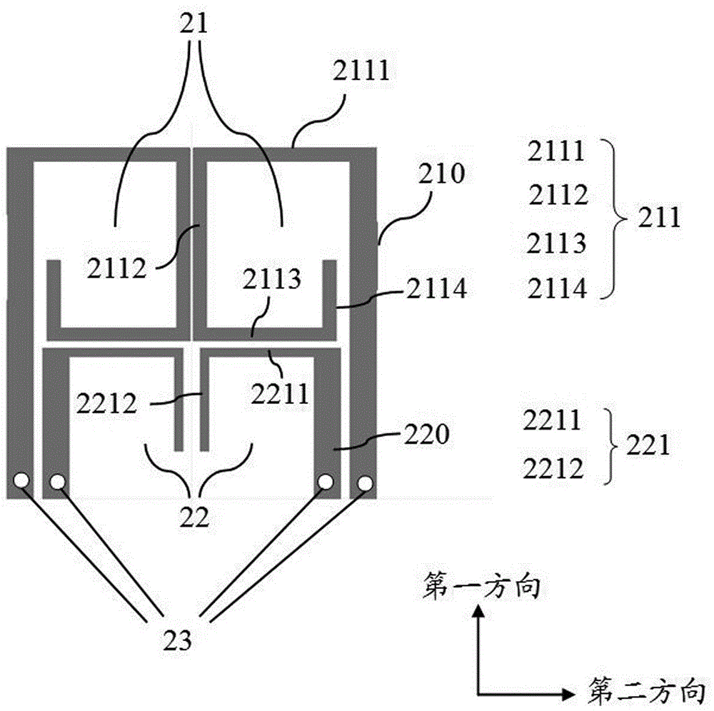
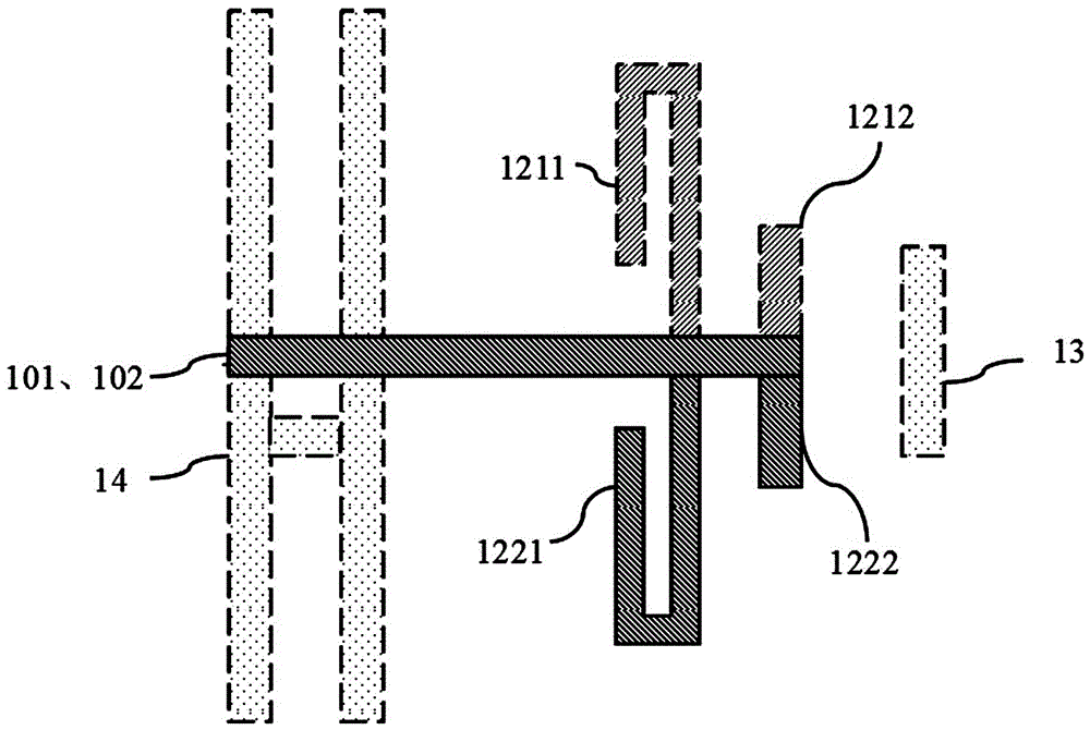
The invention discloses a differential dual-band filtering antenna. The differential dual-band filtering antenna comprises a first substrate, a first radiating unit, a first feeding line, a first dual-band filter, a second substrate, a second radiating unit, a second feeding line, a second dual-band filter, an H-shaped grounding plate and a director, wherein the first radiating unit, the first feeding line and the first dual-band filter are arranged on an upper surface of the first substrate, the first dual-band filter is inserted into the first feeding line, the second substrate is opposite to the first substrate, the second radiating unit, the second feeding line and the second dual-band filter are arranged on a lower surface of the second substrate, the second dual-band filter is inserted into the second feeding line, the H-shaped grounding plate and the director are arranged between a lower surface of the first substrate and an upper surface of the second substrate, the two groups of radiating units are symmetrically arranged relative to the first feeding line and the second feeding line, and the two groups of dual-band filters are arranged in a lamination way and are connected to the H-shaped grounding plate through via holes. A coupling between resonators of the dual-band filters is formed by folding, a radiating zero point can be introduced to the exterior of two frequency bands of the filtering antenna, the selectivity of the filtering antenna is improved very well, and moreover, the impedance bandwidth of the filtering antenna can be improved by adjusting the positions of the dual-band filters inserted into the feeding lines.

Description

technical field [0001] The invention relates to the technical field of electromagnetic compatibility and antennas, in particular to a dual-band filter antenna. Background technique [0002] With the rapid development of wireless communication technology, higher requirements are put forward for modern microwave and wireless communication systems. It is necessary for the parts of the system to be compact, low in cost, low in power consumption, and more importantly, be able to withstand the surrounding environment. Impact. When the system is processing analog signals, the performance of the system is degraded due to the influence of environmental noise and electrical noise of the device. In addition, antennas and filters are key components of the RF front-end, and their performance and size directly affect the overall performance and volume of the entire system. It is particularly important to co-design the filter and the antenna and make it work in the two working frequency ...

Claims


Application Information

Patent Timeline
Patent Type & Authority Applications(China)
IPC IPC(8): H01Q1/38H01Q1/52H01P1/203
CPCH01P1/203H01Q1/38H01Q1/52
Inventor 陈新伟张文梅韩丽萍马润波韩国瑞李莉耿彦峰
Owner SHANXI UNIV
Learn More