
Spacecraft separator based on electromagnetic force

A spacecraft and separator technology, applied in the direction of permanent magnet clutch/brake, etc., can solve the problems of imaging effect, high power consumption, spacecraft attitude, etc., and achieve short response time, high reliability, and low power consumption. Effect

Inactive Publication Date: 2017-01-04
BEIJING INST OF SPACECRAFT ENVIRONMENT ENG
View PDF6 Cites 1 Cited by
  • Summary
  • Abstract
  • Description
  • Claims
  • Application Information

AI Technical Summary

Problems solved by technology

The advantage of pyrotechnic cutting and separation is high reliability, but the disadvantage is that it is easy to cause pollution to the spacecraft and has a certain reaction force. If it is a large pyrotechnic product, the reaction force generated by it will slightly affect the attitude of the spacecraft. influences
In addition, the deployment of optical equipment on some spacecraft, such as cameras and other equipment, will try to avoid the use of pyrotechnics, because pyrotechnics may produce pollutants attached to the lens surface of the camera, which will seriously affect the imaging effect
The advantage of memory alloy separation is that it avoids pollution and force, but its disadvantages are that the mass and volume of the mechanism are relatively large, the power consumption is large, and the separation depends on heating operation, and the action cannot be completed in an instant, so the reliability of separation is not high. very high

Method used


Image

  • Spacecraft separator based on electromagnetic force
  • Spacecraft separator based on electromagnetic force

Examples


Embodiment Construction

[0021] The separator for spacecraft based on electromagnetic force of the present invention will be further described below in conjunction with the accompanying drawings. This description is only exemplary and is not intended to limit the protection scope of the present invention.

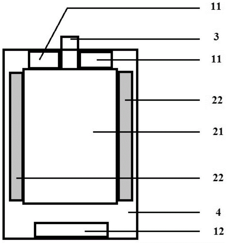
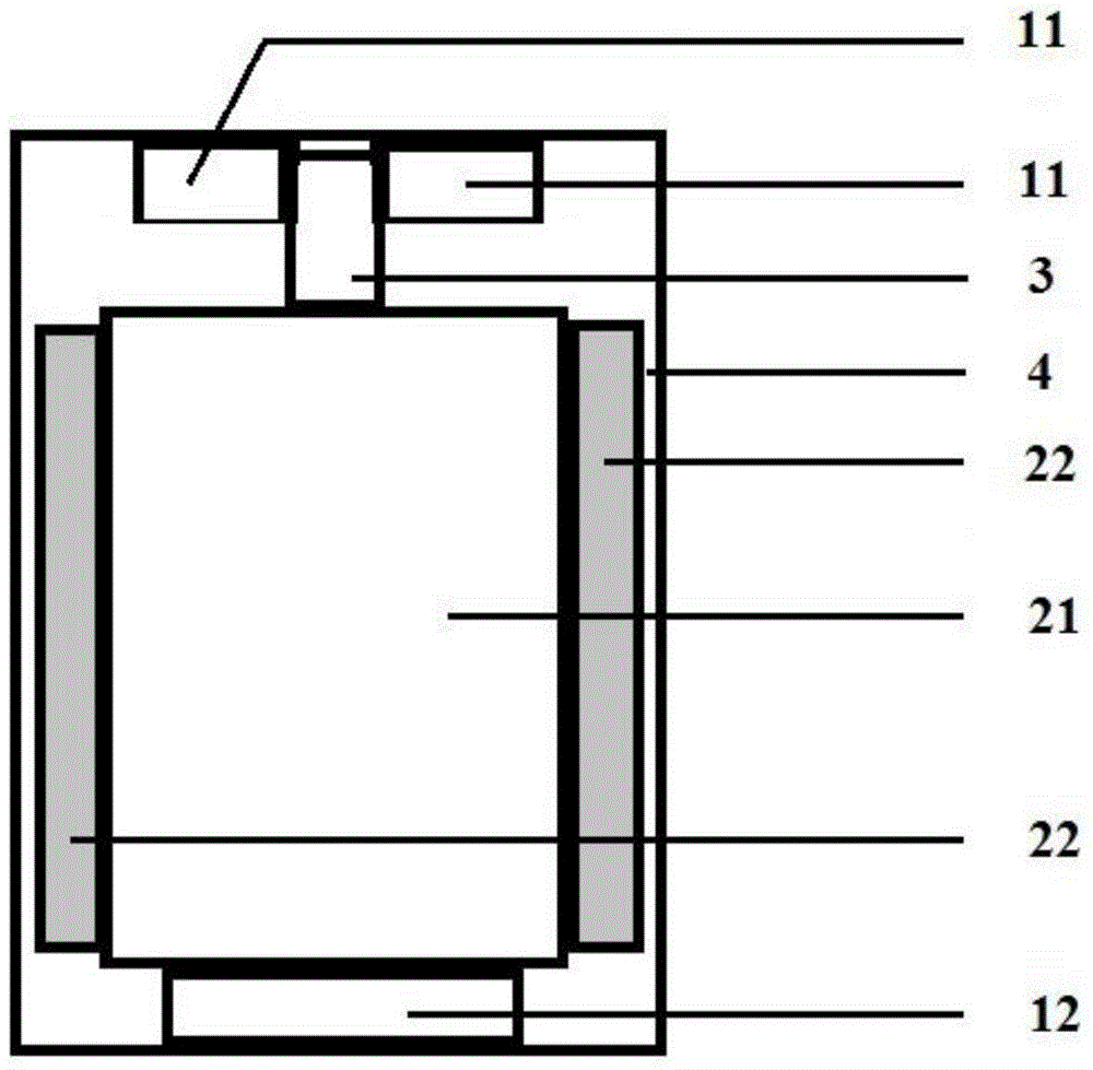
[0022] The separation action of the separator for spacecraft based on electromagnetic force of the present invention relies on electromagnetic force to complete, figure 1 The middle is the structural schematic diagram of the spacecraft separator based on electromagnetic force in the locked state, figure 2 It is a structural schematic diagram of the electromagnetic force-based spacecraft separator in the unlocked state.

[0023] The permanent magnet combined structure that this method uses is as figure 1 As shown, there are two upper repulsive magnets 11, which are fixed on the inner upper surface of the housing 4 by adhesive bonding or screw bolting. The permanent magnets are usually made of NdFe...


PUM


Abstract

The invention discloses a spacecraft separator based on electromagnetic force, comprising upper repulsion magnets, a lower attraction magnet, a soft magnetic core, an electromagnetic coil, a pin spring, and a shell. The lower attraction magnet is arranged in the bottom center inside the shell. The soft magnetic core is arranged over the lower attraction magnet. The electromagnetic coil is wound around the side of the soft magnetic core. The pin spring is integrally arranged in the top center. The upper repulsion magnets are arranged on the top inside the shell, and the center of the top is provided with a shell groove. The pin spring protrudes from the shell via the shell groove and drives the soft magnetic core to leave the lower attraction magnet so as to realize locking; and under the attraction between the soft magnetic core and the lower attraction magnet, the electromagnetic coil and the pin spring move backward together, the part of the pin spring protruding from the shell retracts into the shell, and thus, the purpose of separation is achieved. Compared with the prior art, the separator is quick in response, and can complete action instantaneously to realize unlocking. The implementing mechanism has the advantages of low weight, low power consumption and high reliability.

Description

technical field [0001] The invention belongs to the technical field of spacecraft platform products, and mainly relates to an electromagnetic pin-pull separator with light weight, small volume and high reliability. The separator of the present invention uses a lock-type pin spring to lock the target, and the pin spring is retracted by electromagnetic force to achieve the purpose of pulling out the pin and separating it. Background technique [0002] The on-orbit state of the spacecraft requires many operations to rely on the separator. At present, the commonly used separators on the spacecraft mainly include pyrotechnic cutting and separation, and memory alloy separation. The advantage of pyrotechnic cutting and separation is high reliability, but the disadvantage is that it is easy to cause pollution to the spacecraft and has a certain reaction force. If it is a large pyrotechnic product, the reaction force generated by it will slightly affect the attitude of the spacecraft...

Claims


Application Information

Patent Timeline
IPC IPC(8): H02K49/10
Inventor 耿晓磊张文彬易忠孟立飞肖琦张琼予张艳景李娜王琪
Owner BEIJING INST OF SPACECRAFT ENVIRONMENT ENG
Learn More