A solar tracking device for photovoltaic power generation
A solar tracking and photovoltaic power generation technology, applied in the field of solar tracking devices, can solve the problems of large-scale application of tracking brackets, poor adaptability to the environment, and large foundation volume, etc., to achieve large-scale design, convenient construction and maintenance, The effect of increasing power generation
- Summary
- Abstract
- Description
- Claims
- Application Information
AI Technical Summary
Problems solved by technology
Method used
Image
Examples
Embodiment 1
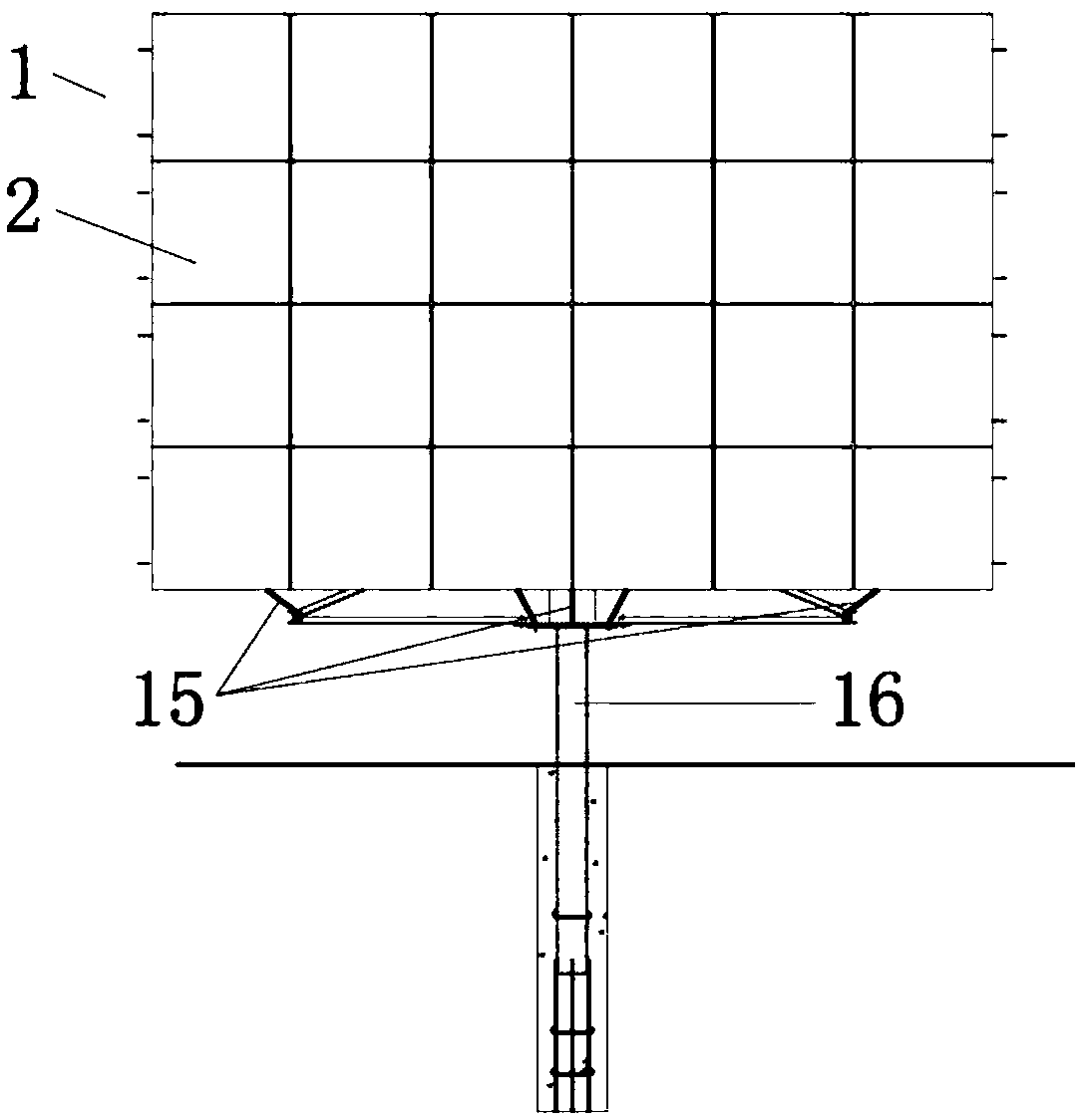
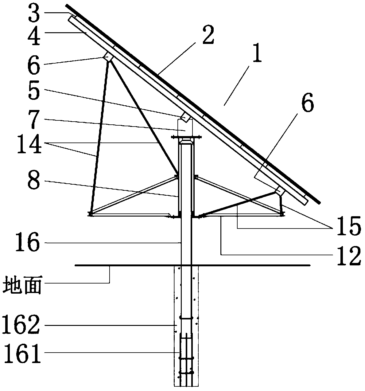
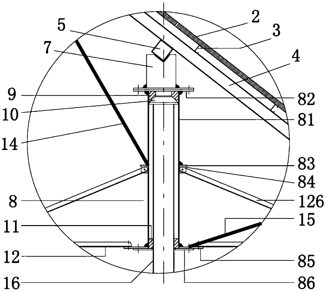
[0057] Such as figure 1 , 2 , 3, and 5, the tracking bracket 1 includes: a pile 16, a casing 8, a steel wheel 12, and a photovoltaic module plate fixing plate;
[0058] The pile 16 is a steel pipe or reinforced concrete material with a circular cross-section, which can be solid or hollow. The part embedded in the ground is called a pile, and the protruding part is called a column. And in order to enhance the anchoring effect on the ground, the bottom of the pile 16 is welded with an anchor bar 161, and the periphery of the buried part is poured and compacted with concrete 162. The axis line of the pile column 16 is perpendicular to the ground. When the pile 16 is made of steel pipe material, concrete is poured into the steel pipe to greatly improve the bending, shearing and torsional performance of the pile 16;
[0059] The photovoltaic module board 2 is installed on the horizontal purlin 3, and the horizontal purlin 3 is installed on the inclined beam 4, and the inclined b...
Embodiment 2
[0076] Such as Figure 4As shown, the only difference from the first implementation is that the combined structure of the pile 16 and the casing 8 has another form. The vertical support force of the pile 16 to the casing 8 is not at the top of the pile 16, but at the top of the casing 8. bottom of. A support flange 163 is welded at the waist of the pile 16. When the sleeve is inserted into the pile, the bottom surface of the sleeve 8 just sits on the surface of the support flange 163, forming the vertical support of the pile 16 to the sleeve 8. The upper surface of the large flange 163 and the bottom surface of the sleeve pipe 8 and the flange 85 at the bottom of the pipe are the sliding friction surfaces. In the inner cavity of the casing 8, two radial positioning bearings are set to realize the radial positioning support. The lower radial positioning support is a split bearing bush 11, and the upper radial positioning support is a circular sleeve 111. There is a supporting...
Embodiment 3
[0079] Such as Figure 17 As shown, on the basis of the tracking bracket in Embodiment 1, firstly, the connection mode between the inclined beam 4 and the horizontal beam 5 is changed to the connection mode of the hinge 24, and the inclined beam 4 can rotate around the axis of the hinge 24, and the high position The horizontal subbeam 6 and the high subbeam support rod 14 or the low subbeam support rod 15 under the horizontal subbeam 6 of the low position are changed to the high position adjustable support rod 141 and the low position adjustable support rod 151 of the telescopic adjustment length, and the high position The upper and lower ends of the adjustable support rod 141 and the low-position adjustable support rod 151 are connected by hinges, and a triangular support bracket 25 and a push rod support 29 are added to the casing 8, and finally a simple manual push rod 26 is set, and the Use the manual push rod 2 to adjust the inclination angle of the photovoltaic module bo...
PUM
 Abstract
Description
Claims
Application Information
 - R&D
- Intellectual Property
- Life Sciences
- Materials
- Tech Scout
- Unparalleled Data Quality
- Higher Quality Content
- 60% Fewer Hallucinations
Browse by: Latest US Patents, China's latest patents, Technical Efficacy Thesaurus, Application Domain, Technology Topic, Popular Technical Reports.
© 2025 PatSnap. All rights reserved.Legal|Privacy policy|Modern Slavery Act Transparency Statement|Sitemap|About US| Contact US: help@patsnap.com


