
A control method and device for a Doherty power amplifier

A control method and power technology, which is applied to parts of amplifiers, amplifiers, improved amplifiers to improve efficiency, etc., can solve the problems of Doherty power amplifier efficiency decline, large thermal power consumption of circuits, etc., to ensure linearity and improve Efficiency, the effect of reducing thermal power consumption

Active Publication Date: 2020-06-16
DYNAX SEMICON
View PDF3 Cites 0 Cited by
  • Summary
  • Abstract
  • Description
  • Claims
  • Application Information

AI Technical Summary

Problems solved by technology

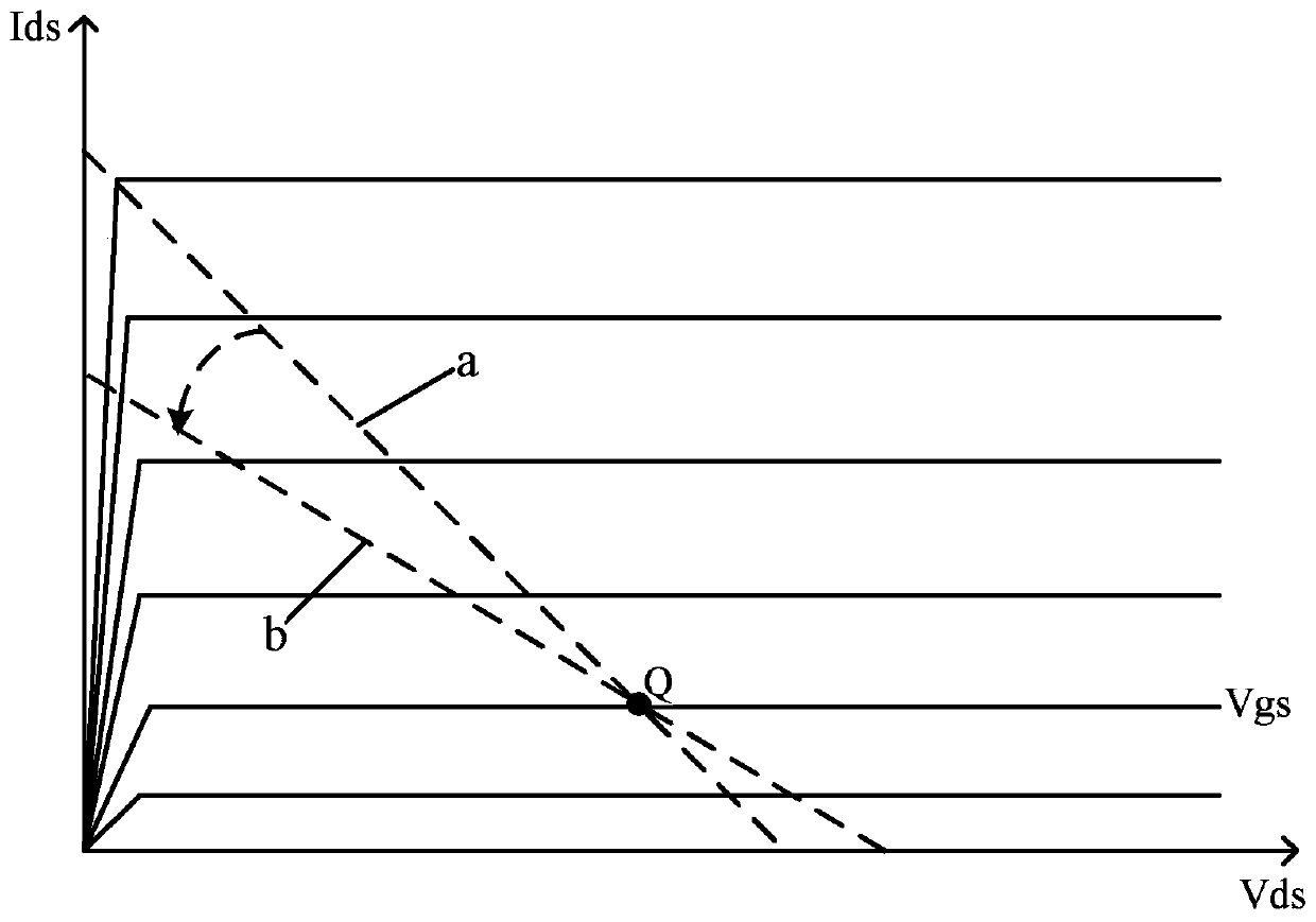
[0004] However, in order to ensure that the Doherty power amplifier has good linearity, in the process of changing the load line of the carrier power amplifier from load line a to load line b, the carrier power amplifier in the prior art must always work in class AB, and the carrier power amplifier's The static operating point is always located at figure 2 The Q point in the carrier makes the thermal power consumption of the carrier power amplifier circuit larger, which directly leads to the decline of the efficiency of the Doherty power amplifier.

Method used


Image

  • A control method and device for a Doherty power amplifier
  • A control method and device for a Doherty power amplifier
  • A control method and device for a Doherty power amplifier

Examples


Embodiment 1

[0049] The Doherty power amplifier provided by the present invention may be a two-way balanced Doherty power amplifier, a two-way unbalanced Doherty power amplifier, a multi-way Doherty power amplifier or a multi-stage Doherty power amplifier. In this embodiment, a two-way Doherty power amplifier is taken as an example for illustration.

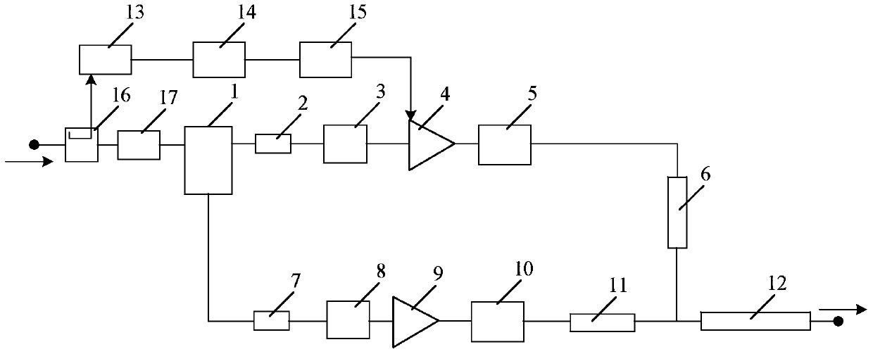
[0050] image 3 It is a schematic circuit diagram of the Doherty power amplifier and its control device provided by Embodiment 1 of the present invention. Such as image 3 As shown, the radio frequency signal is divided into two paths through the coupler 16, one path is output from the output end of the coupler 16, enters the Doherty power amplifier through the delay circuit, and the other path is output through the coupling end of the coupler 16, and then passes through the detector 13. The digital signal processing circuit 14 and the grid voltage regulating circuit output the regulation voltage to the grid of the carrier power amplifier 4; ...

Embodiment 2

[0069] Image 6 It is a structural block diagram of a control device for a Doherty power amplifier provided in Embodiment 2 of the present invention. Such as Image 6 As shown, the device includes a Doherty power amplifier output state acquisition module 20 , a Doherty and grid voltage regulation module 30 .

[0070] Wherein, the Doherty Doherty power amplifier output state detection module 20 is used to detect the output state of the Doherty power amplifier, and the Doherty power amplifier includes a carrier power amplifier and a peak power amplifier Doherty Doherty;

[0071] The grid voltage adjustment module 30 is used to adjust the grid voltage of the carrier power amplifier according to the output state of the Doherty power amplifier, so that the output power of the carrier power amplifier in the Doherty power amplifier drops from a saturated state to a process corresponding to the fallback amount , switch from Class B working status to Class AB working status.

[0072...


PUM


Abstract

The present invention discloses a Doherty power amplifier control method and apparatus, wherein the method comprise: obtaining an output state of a Doherty power amplifier, wherein the Doherty power amplifier comprises a carrier power amplifier and a peak value power amplifier; and adjusting a grid voltage of the carrier power amplifier according to the output state of the Doherty power amplifier, so that the carrier power amplifier switches from a B-type working state to an AB-type working state in a process in which output power of the Doherty power amplifier decreases from a saturation state to power corresponding to a regression amount of the Doherty power amplifier. According to the Doherty power amplifier control method and apparatus, the grid voltage of the carrier power amplifier is adjusted according to the output state of the Doherty power amplifier, to change a working state of the carrier power amplifier, thereby improving efficiency of the Doherty power amplifier and ensuring linearity of the Doherty power amplifier.

Description

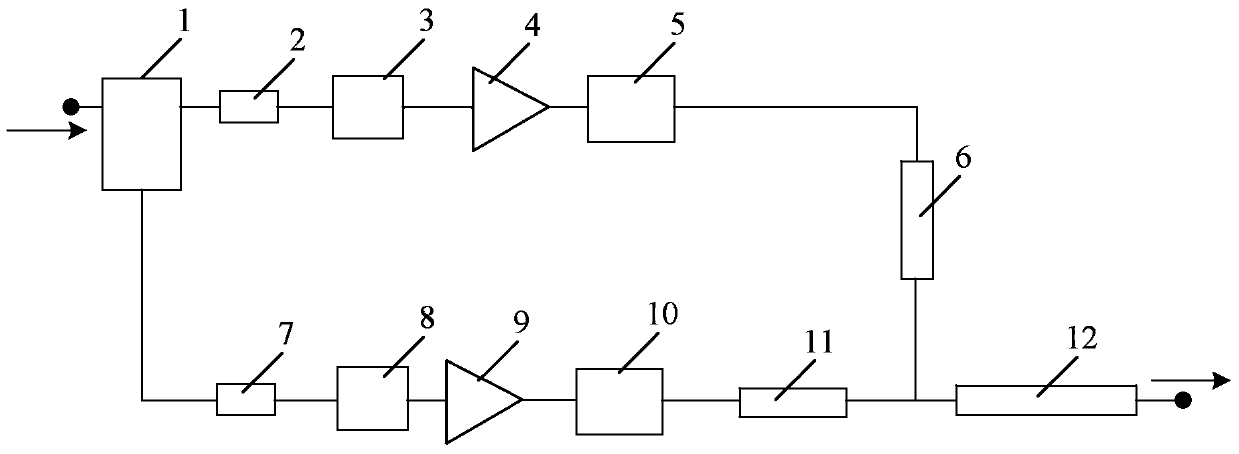
technical field [0001] The invention relates to the technical field of wireless communication, and relates to a control method and device for a Doherty power amplifier. Background technique [0002] Efficiency and linearity are the two most important indicators of a communication system. Efficiency directly affects the operating cost of the communication system, and linearity determines the communication quality. The combination of Doherty power amplifier (ie, Doherty power amplifier) ​​and digital pre-distortion (Digital Pre-Distortion, DPD) is a common technology in modern wireless communication. [0003] Doherty power amplifier adopts active load modulation technology, and the whole power amplifier can be composed of two parallel power amplifier circuits, such as figure 1 shown. After the RF signal enters the Doherty power amplifier, it is divided into two paths by the power divider 1, and one path of the RF signal passes through the first microstrip line 2, the first ...

Claims


Application Information

Patent Timeline
Patent Type & Authority Patents(China)
IPC IPC(8): H03F1/02H03F1/32
CPCH03F1/0288H03F1/32
Inventor 杨天应张永胜张乃千
Owner DYNAX SEMICON
Learn More