Linear LED drive circuit for silicon controlled dimming

A technology of LED drive and drive circuit, applied in the direction of light source, electric light source, electrical components, etc., can solve the problem of switch flickering, etc., and achieve the effect of smooth and excellent dimming effect

Inactive Publication Date: 2017-01-04
成都锦瑞芯科技有限公司
View PDF5 Cites 8 Cited by
  • Summary
  • Abstract
  • Description
  • Claims
  • Application Information

AI Technical Summary

Problems solved by technology

[0009] In view of the above prior art, the purpose of the present invention is to provide a linear LED drive circuit for thyristor dimming, which solves the overshoot flicker at the turn-on moment of the prior art and the switch caused by repeatedly switching channels when the critical voltage reaches Technical problems such as flickering

Method used


Image

  • Linear LED drive circuit for silicon controlled dimming
  • Linear LED drive circuit for silicon controlled dimming
  • Linear LED drive circuit for silicon controlled dimming

Examples


Embodiment 1

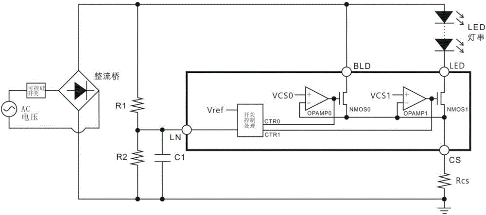
[0047] The main circuit adopted in the present invention includes a bus voltage sampling integration circuit, a bus voltage signal processing circuit, a thyristor maintaining current circuit, and an LED constant current control circuit.

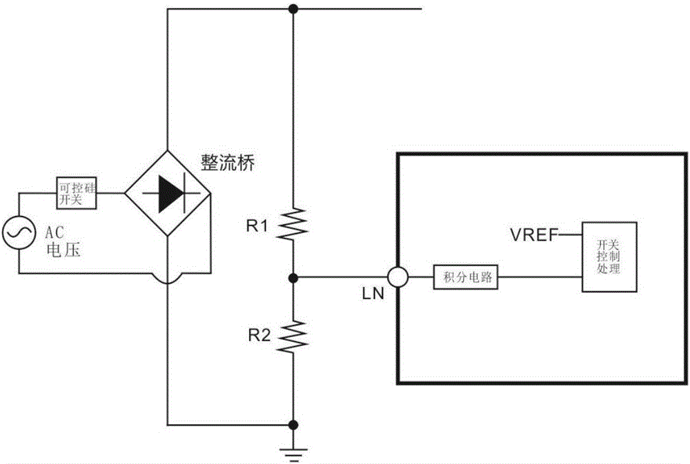
[0048] like figure 1 As shown, R1 / R2 / C1 forms a bus voltage sampling integration circuit. The main function of this circuit is to divide the bus voltage and integrate it through RC to get a stable DC voltage and send it to the LN terminal. The signal LN will be used to control the switching control between the SCR maintaining current circuit and the LED constant current control circuit. The advantage of using the integral circuit is that it can effectively avoid the LED light from being turned on by mistake due to the surge voltage at the moment the thyristor is turned on, and it is easy to see the light flickering phenomenon. At the same time, during the dimming process, if there is no processing by the integrating circuit, the LED light w...


PUM


Abstract

The invention relates to the technical field of LED drive circuits, in particular to a linear LED drive circuit for silicon controlled dimming. The technical problems that in the prior art, when overshoot flicker at the turn-on moment is achieved and critical voltage is reached, channels are switched repeatedly to cause switch flicker are solved. The linear LED drive circuit mainly comprises a power source, a silicon controlled switching circuit, a rectifier bridge, an integral circuit and a drive circuit, wherein a silicon controlled drive power circuit is formed by the power source, the silicon controlled switching circuit and the rectifier bridge; the integral circuit comprises a power source potential point and a sampling potential point, wherein the voltage values of the power source potential point and the sampling potential point are reduced in sequence, and the output end of the rectifier bridge is connected to the power source potential point; the drive circuit comprises a switch control and processing circuit, and the switch control and processing circuit controls a first switch transistor of a drive circuit discharge channel and a second switch transistor of a drive circuit LED channel to be connected or disconnected through voltage of the sampling potential point; the switch control and processing circuit comprises a hysteresis comparator and an LED lamp, the input end of the hysteresis comparator is connected to the sampling potential point, and the maximum potential point of the LED lamp is connected with the output end of the rectifier bridge. The invention is used for designing the LED drive circuit.

Description

technical field [0001] The invention relates to the technical field of LED driving circuits, in particular to a linear LED driving circuit for dimming with silicon controlled rectifiers. Background technique [0002] In the LED linear drive structure, the circuit used for thyristor dimming is commonly seen as Figure 12 shown. The thyristor discharge circuit is usually a separate discharge circuit, which discharges through the BLD channel, while the LED current passes through another channel. When the thyristor switch is turned on, because the voltage above the bus voltage is not high enough, the LED channel cannot be turned on. At this time, the BLD channel is turned on to provide the maintenance current of the thyristor switch. As the conduction angle of the thyristor switch increases, when the bus voltage is high enough, the LED channel starts to conduct. Generally, the voltage of VREF1 is set to be lower than the voltage of VREF2 inside the IC, so when the current of t...

Claims


Application Information

Patent Timeline
Patent Type & Authority Applications(China)
IPC IPC(8): H05B33/08H05B44/00
CPCH05B45/00Y02B20/30
Inventor 孙晓良俞德军
Owner 成都锦瑞芯科技有限公司
Why Eureka
Try Eureka