
Integrated waste water treatment equipment

A technology for sewage treatment equipment and boxes, applied in water/sewage treatment equipment, water/sewage treatment, water/sludge/sewage treatment, etc. 16 Inconvenient installation and other problems, to achieve the effect of small footprint and convenient use

Inactive Publication Date: 2017-01-11
四川乐根水处理设备有限公司
View PDF8 Cites 21 Cited by
  • Summary
  • Abstract
  • Description
  • Claims
  • Application Information

AI Technical Summary

Problems solved by technology

[0002] At present, when the coagulation and sedimentation method is used in the treatment of sewage with a small flow rate (≤100m3 / h) in China, the coagulation tank and the sedimentation tank are often used as two independent units. The coagulation tank is mechanically stirred, and the elevation is high. The pool adopts the inclined pipe 16 for sedimentation, and the elevation is low. The sewage after the coagulation reaction directly enters the sedimentation tank of the inclined pipe 16 vertically through the connecting pipe, that is, the connecting pipe is vertically connected to the water distributor at the bottom of the inclined pipe 16 sedimentation tank. At a certain height, dynamic sludge discharge is often used for sludge discharge, and the water distributor at the bottom of the sedimentation tank where the connecting pipe is vertically connected to the inclined pipe 16 will cause inconvenient installation of the inclined pipe 16 next to the vertical pipeline in the sedimentation tank, and the dynamic sludge discharge needs to consume a certain amount of energy. And because it is two independent units, the floor area is relatively large

Method used


Image

  • Integrated waste water treatment equipment

Examples


Embodiment Construction

[0015] The invention will be described in further detail below through specific implementation examples and in conjunction with the accompanying drawings.

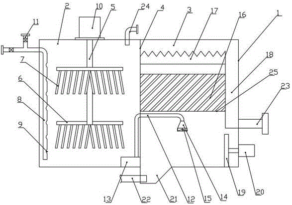
[0016] figure 1 The integrated sewage treatment equipment provided by the invention is shown, comprising a casing 1, a partition 4 that divides the casing 1 into a stirring chamber 2 and a sedimentation chamber 3, the partition 4 is arranged in the middle of the casing 1, and makes the stirring The chamber 2 and the precipitation chamber 3 are distributed left and right; the stirring chamber 2 is equipped with a stirring shaft 5; the stirring shaft 5 is equipped with a fixed frame 6, and the fixed frame 6 is hingedly equipped with a stirring blade 7, and the stirring blade 7 is installed On the lower surface of the fixed mount 6, the stirring blade 7 can swing freely on the fixed mount 6; a vertical dosing pipeline 8 is also arranged in the tank body, and a plurality of medicine feeding holes 9 are provided on the dosing p...


PUM


Abstract

The invention discloses integrated waste water treatment equipment, and relates to the technical field of waste water treatment. The integrated waste water treatment equipment comprises a box body and a partition board for dividing the box body into a stirring chamber and a settling chamber; a stirring shaft is arranged in the stirring chamber; a fixed mount is arranged on the stirring shaft, and stirring blades are arranged onto the fixed mount in an articulated manner; a vertical dosing pipeline is further arranged in the box body, and a plurality of medicament feeding holes are formed in the dosing pipeline; the box body is further internally provided with a conveying pipeline for communicating the stirring chamber with the settling chamber; the settling chamber is further internally provided with a net plate, the net plate is positioned above a water outlet, and honeycomb inclined tubes are arranged on the net plate; an overflow plate is further arranged above the inclined tubes; a clean water storage tank is further arranged in the settling chamber; a vertical push plate is further arranged at the bottom of the settling chamber, a pushing device is further arranged on the box body, and the pushing device is fixed with the push plate. According to the integrated waste water treatment equipment, stirring and settling of waste water can be completed at one time, and the equipment is more convenient to use.

Description

technical field [0001] The invention relates to the technical field of sewage treatment, in particular to an integrated sewage treatment equipment. Background technique [0002] At present, when the coagulation and sedimentation method is used in the treatment of sewage with a small flow rate (≤100m3 / h) in China, the coagulation tank and the sedimentation tank are often used as two independent units. The coagulation tank is mechanically stirred, and the elevation is high. The pool adopts the inclined pipe 16 for sedimentation, and the elevation is low. The sewage after the coagulation reaction directly enters the sedimentation tank of the inclined pipe 16 vertically through the connecting pipe, that is, the connecting pipe is vertically connected to the water distributor at the bottom of the inclined pipe 16 sedimentation tank. At a certain height, dynamic sludge discharge is often used for sludge discharge, and the water distributor at the bottom of the sedimentation tank w...

Claims


Application Information

Patent Timeline
IPC IPC(8): B01D21/08B01D21/24C02F1/52
CPCB01D21/0039B01D21/0042B01D21/08B01D21/245C02F1/5281C02F2201/002
Inventor 杜贵
Owner 四川乐根水处理设备有限公司
Learn More