Eureka AIR delivers breakthrough ideas for toughest innovation challenges, trusted by R&D personnel around the world.

Photocatalytic compound exhaust gas treatment system

A waste gas treatment and composite technology, which is applied in the direction of combined devices, gasification substances, chemical instruments and methods, etc., can solve problems such as conflicts of energy saving and consumption reduction, limited use, easy cracking of pipes, etc., and achieve the effect of improving efficiency

Inactive Publication Date: 2017-01-11
SHIYAN DONGHUAN ENVIRONMENTAL PROTECTION EQUIP
View PDF3 Cites 9 Cited by
  • Summary
  • Abstract
  • Description
  • Claims
  • Application Information

AI Technical Summary

Problems solved by technology

[0002] The country pays more and more attention to environmental protection. At present, the waste gas treatment technology on the market relies on UVC tubes to crack and oxidize the waste gas components. The effect will be greatly affected (UVC tube, the ideal temperature is within 75 degrees Celsius, if it exceeds this temperature, the ability to crack the molecular bonds of exhaust gas will be weakened, and the tube will be easily broken); single UVC photolysis technology, the composition The effect of complex waste gas treatment is not ideal, and the method of only increasing the power is a waste of energy, which conflicts with energy saving and consumption reduction
[0005] CN 203916427U A kind of photocatalytic organic waste gas treatment system, has adopted ultraviolet lamp tube and TiO2 coating, the detoxification action of ultraviolet lamp combines the reaction of TiO2 to have played a certain role, but the UVC tube of ultraviolet lamp tube, ideal temperature is 75 degrees centigrade If it exceeds this temperature, the ability to crack the molecular bonds of exhaust gas will be weakened, and the tube will be easily broken, so there are certain limitations in its use.

Method used


Image

  • Photocatalytic compound exhaust gas treatment system

Examples


Embodiment Construction

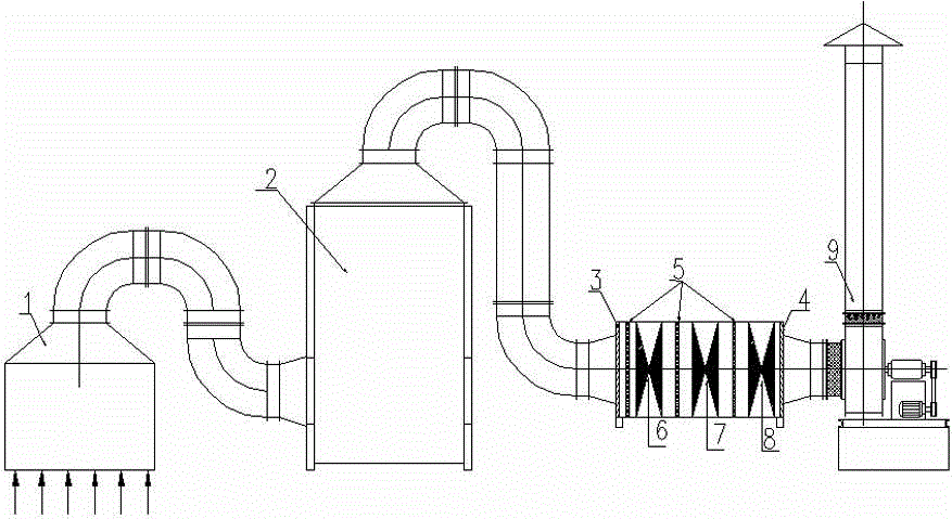
[0019] The present invention as figure 1 shown.

[0020] A photocatalytic composite exhaust gas treatment system, comprising an exhaust gas collection cover 1, the exhaust gas collection cover 1 is connected with a spray tower 2, the spray tower 2 is connected with a photo-oxygen catalytic device, and the photo-oxygen catalytic device is connected with an induction Wind device 9; filter 3 through the first filter screen between the photo-oxygen catalytic device and the spray tower 2, and filter through the second filter screen 4 between the photo-oxygen catalytic device and the draft device 9; Multi-channel TiO2 filter screen, UVC tube and ozone generator, wherein the multi-channel TiO2 filter screen 5 and UVC tube and ozone generator are arranged at intervals.

[0021] There are three TiO2 filter screens 5, UVC tubes and ozone generators, wherein the TiO2 filter screens are set behind the first filter screen, and then the first UVC tube and ozone generator 6, TiO2 filter scr...


PUM


Abstract

The invention relates to a photocatalytic compound exhaust gas treatment system. An exhaust gas collecting cover is connected with a spray tower, the rear part of the spray tower is connected with a photolysis oxidization catalysis device, and the rear part of the photolysis oxidization catalysis device is connected with an air inducing device; a first filter screen is arranged between the photolysis oxidization catalysis device and the spray tower to realize filtration, and a second filter screen is arranged between the photolysis oxidization catalysis device and the air inducing device to realize filtration; and a plurality of TiO2 filter screens and a plurality of UVC tubes and ozone generators are arranged in the photolysis oxidization catalysis device at intervals. A spraying technology is used to cool exhaust gas and remove one part of dusts in the exhaust gas, so primary purification and maintenance of cleanness of the UVC tubes are realized; a catalyst is arranged, so the photolysis oxidization efficiency is greatly improved under the catalysis of the catalyst; and high temperature exhaust gas or exhaust gas with complex components is cooled and washed, enters the photolysis oxidization device and undergoes secondary treatment, so disadvantages of single technologies are overcome.

Description

technical field [0001] The invention relates to a waste gas treatment system in environmental protection equipment, in particular to a photocatalytic composite waste gas treatment system. Background technique [0002] The country pays more and more attention to environmental protection. At present, the waste gas treatment technology on the market relies on UVC tubes to crack and oxidize the waste gas components. The effect will be greatly affected (UVC tube, the ideal temperature is within 75 degrees Celsius, if it exceeds this temperature, the ability to crack the molecular bonds of exhaust gas will be weakened, and the tube will be easily broken); single UVC photolysis technology, the composition The effect of complex waste gas treatment is not ideal, and the method of only increasing the power is a waste of energy, which conflicts with energy saving and consumption reduction. [0003] CN 201296683Y discloses a photodegradation device for waste gas and wastewater and its ...

Claims


Application Information

Patent Timeline
IPC IPC(8): B01D53/86B01D53/74B01D53/76B01D50/00A61L9/18A61L9/015
Inventor 张维峰
Owner SHIYAN DONGHUAN ENVIRONMENTAL PROTECTION EQUIP
Why Eureka
Eureka Blog
Learn More