
Crusher, anvil device, anvil piece and mineral production line

A crusher and crushing cavity technology, applied in the fields of crushers and mineral production lines, can solve the problems such as difficulty in reaching a relatively ideal level of crushing efficiency and grain shape effect, affecting the operation of impeller devices, and poor crushing efficiency and crushing grain shape shaping effect.

Active Publication Date: 2017-01-11
ZOOMLION HEAVY IND CO LTD
View PDF9 Cites 0 Cited by
  • Summary
  • Abstract
  • Description
  • Claims
  • Application Information

AI Technical Summary

Problems solved by technology

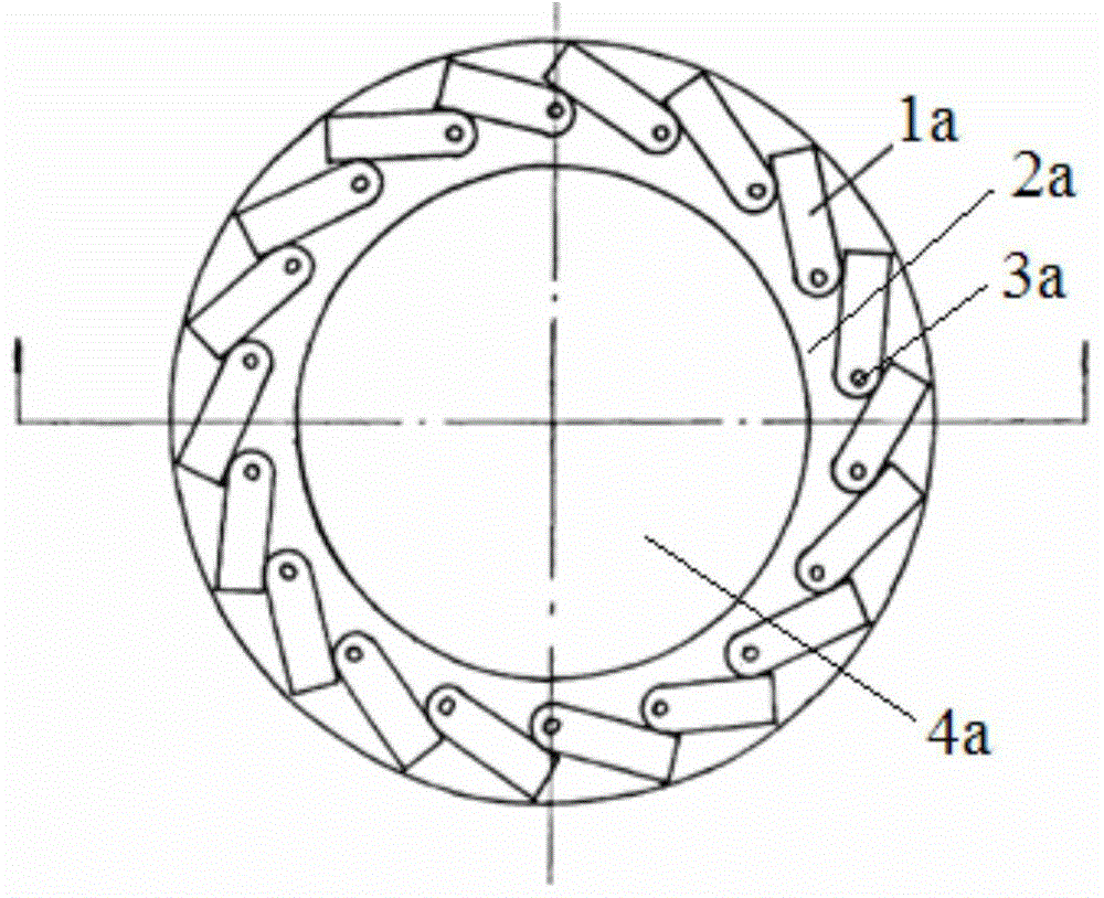
According to the CN95201284.7 description, the annular support step 2a is mainly used to set the liner pillar 3a, and it is not mentioned that the annular support step 2a can form a material lining in the work engineering, but it is precisely because of the annular support step 2a. Existence, which makes it difficult for this crusher to perform crushing work effectively during the working process
As mentioned above, since each counter-attack liner 1a is within the range of the annular support step 2a in the direction of the plan view, the material must be accumulated on the annular support step 2a during the working process of the crusher, thereby forming a material lining, But when figure 1 In the crushing arrangement shown, the material liner layer accumulated on the annular support step 2a will cover the material impact area of ​​the counter-attack liner 1a, which leads to the fact that the main method of material crushing in this crusher is still "material beating material". "The crushing mode, even if the material occasionally rebounds to the exposed impact liner, it cannot play a major role in crushing
figure 1 The more serious defect of the crushing arrangement shown is that, since the material is piled up on the annular support step 2a in large quantities, and the impeller device is constantly throwing out the material, this causes the materials to be jammed with each other and even affects the operation of the impeller device. making it difficult to carry out normal crushing work
Practice has proved that this kind of crusher not only has low crushing efficiency, but also the grain shape of the crushed material particles is worse than the traditional "material beating material" crushing mode
[0009] As another example, the crusher disclosed in the Chinese utility model patent CN2868415Y also claims to adopt the crushing mode of "mixing materials and anvils", but from the analysis of its technical scheme, it mainly alternates along the circumferential direction on the inner surface of the crushing cavity The anvil iron and the material lining are arranged in a perfect manner. During the crushing process of the crusher with this structure, the materials accelerated by the impeller generally only collide with the anvil iron and the material lining layer accumulated on the material lining. In the crusher with this structure, there are actually two crushing modes of "material hitting material" and "material hitting anvil" at the same time, and these two crushing modes are relatively separated from each other. Obviously, the crushing efficiency and The shaping effect of the broken particle type is relatively poor. In order to improve this poor crushing effect, this prior art crusher mainly adopts the adjustment of the ratio of the material lining and the anvil in the crushing chamber, hoping to improve the crushing efficiency. and particle shape effect, but no matter how it is adjusted, practice has proved that its crushing efficiency and particle shape effect are difficult to reach a relatively ideal level

Method used


Image

  • Crusher, anvil device, anvil piece and mineral production line
  • Crusher, anvil device, anvil piece and mineral production line
  • Crusher, anvil device, anvil piece and mineral production line

Examples


Embodiment Construction

[0064] The specific embodiments of the present invention will be described in detail below in conjunction with the accompanying drawings. It should be understood that the specific embodiments described here are only used to illustrate and explain the present invention, and the protection scope of the present invention is not limited to the following specific embodiments. .

[0065] It should be noted in advance that, in the following description of specific embodiments of the present invention, "anvil device", "anvil piece" and the like do not mean that the anvil device and anvil piece of the present invention can only be made of metallic iron, the so-called "Anvil device", "anvil piece" and so on are only general terms for those skilled in the art to impact parts inside the crusher, which can be made of various materials with sufficient hardness to crush materials, such as steel, nickel alloy, etc. In addition, in the following description of the present invention, the orient...


PUM


Abstract

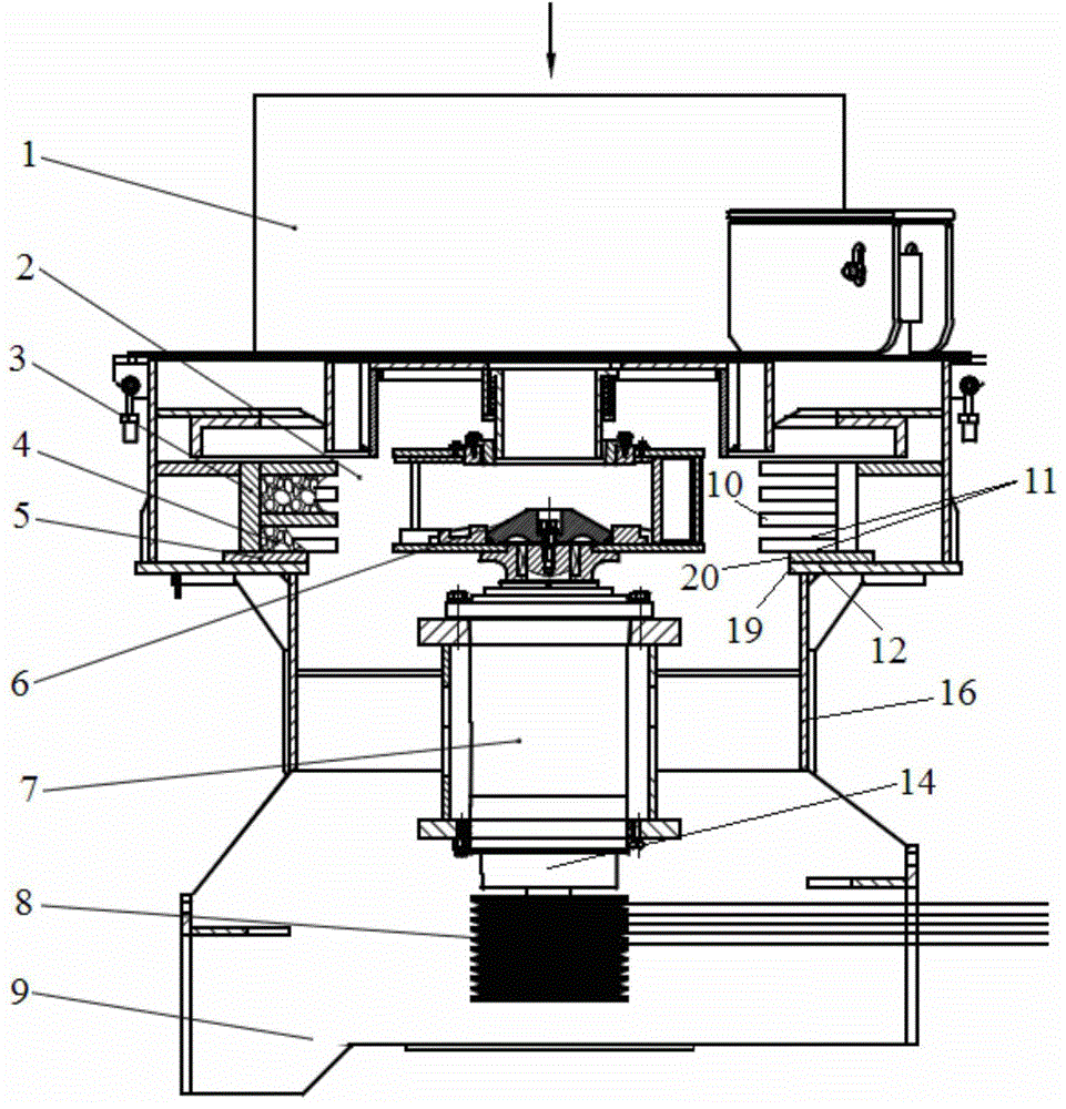
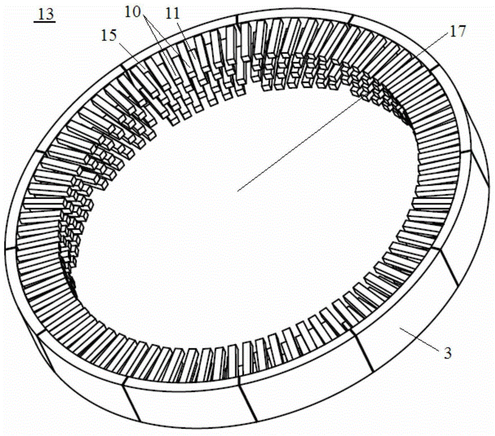
The invention discloses a crusher, an anvil device, an anvil piece of the anvil device and a mineral production line. A crushing cavity (2) of the crusher is internally provided with at least two material impact part layers arranged in the up-down direction. Each material impact part layer comprises a plurality of columnar material impact parts (10) arranged around an impeller device (6) at intervals. In the adjacent material impact part layers in the up-down direction, the material impact parts at the lower layer are arranged to be capable of being stacked into material lining layers (4) to be doubled as material lining forming parts (11) relative to the corresponding material impact parts at the upper layer, and the inner ends of the material impact parts at the lower layer do not exceed the inner ends of the corresponding material impact parts (10) at the upper layer. According to the crusher, the anvil device, the anvil piece of the anvil device and the mineral production line, a crushing pattern that materials and anvils are subjected to mixed striking is truly achieved through an original sequential impact mode; and in addition, the crushing efficiency is high, the crushed grain shape is good, and the voidage of the crushed materials is significantly increased compared with the voidage of materials crushed by existing crushers.

Description

technical field [0001] The present invention relates to a material processing equipment, in particular to a crusher. Further, the present invention relates to an anvil device for a crusher and anvil parts thereof. Furthermore, the invention relates to a mineral production line comprising a crusher. Background technique [0002] Crusher is used for crushing and processing of materials, and it is widely used in fields that require crushing and processing of materials, such as mineral processing and production industries, construction industries, food processing industries, etc. The most widely used crusher is the impact crusher, which mainly crushes materials through mechanical impact and collision. In the process of crushing materials, impact crushers often also have requirements for the shape of the crushed materials (that is, particle shape), so impact crushers can also be called "crushing and shaping machines", such as those used in sand and gravel processing. The shapi...

Claims


Application Information

Patent Timeline
IPC IPC(8): B02C13/282
Inventor 黄露黄柯徐建华
Owner ZOOMLION HEAVY IND CO LTD
Learn More