
Arc fuse additive manufacturing method for a disc-shaped support

An additive manufacturing and support technology, applied in the field of additive manufacturing, arc fuse additive manufacturing of TIG power supply, and arc fuse additive manufacturing, which can solve the problem of heavy programming workload, repeated positioning and difficulty in finding, Low level of intelligence, etc.

Active Publication Date: 2018-06-01
CAPITAL AEROSPACE MACHINERY +1
View PDF8 Cites 0 Cited by
  • Summary
  • Abstract
  • Description
  • Claims
  • Application Information

AI Technical Summary

Problems solved by technology

At present, the intelligence of arc fuse additive manufacturing technology is low, and it is not enough to realize the direct conversion from 3D digital model to robot control language. It is necessary to manually analyze the characteristics of the 3D model, and then formulate the forming strategy and plan the forming path. Finally realize the preparation of the robot program
[0003] At present, in robot programming, the teaching method is generally used to determine the position of the teaching point. The teaching point is basically determined by the naked eye, and it is difficult to repeat positioning and alignment. The more complex the workpiece, the more the number of teaching points will greatly increase the workload. , resulting in low programming efficiency and accuracy
In the arc fuse additive manufacturing process, when the program is interrupted and restarted, it is generally necessary to modify the teaching point of the program, so that the position accuracy of the teaching point is not high, the programming workload is large, and the portability is not high

Method used

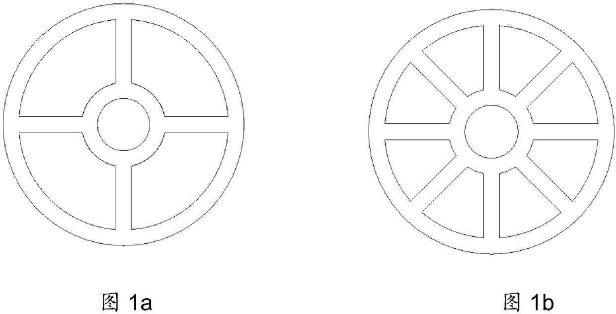
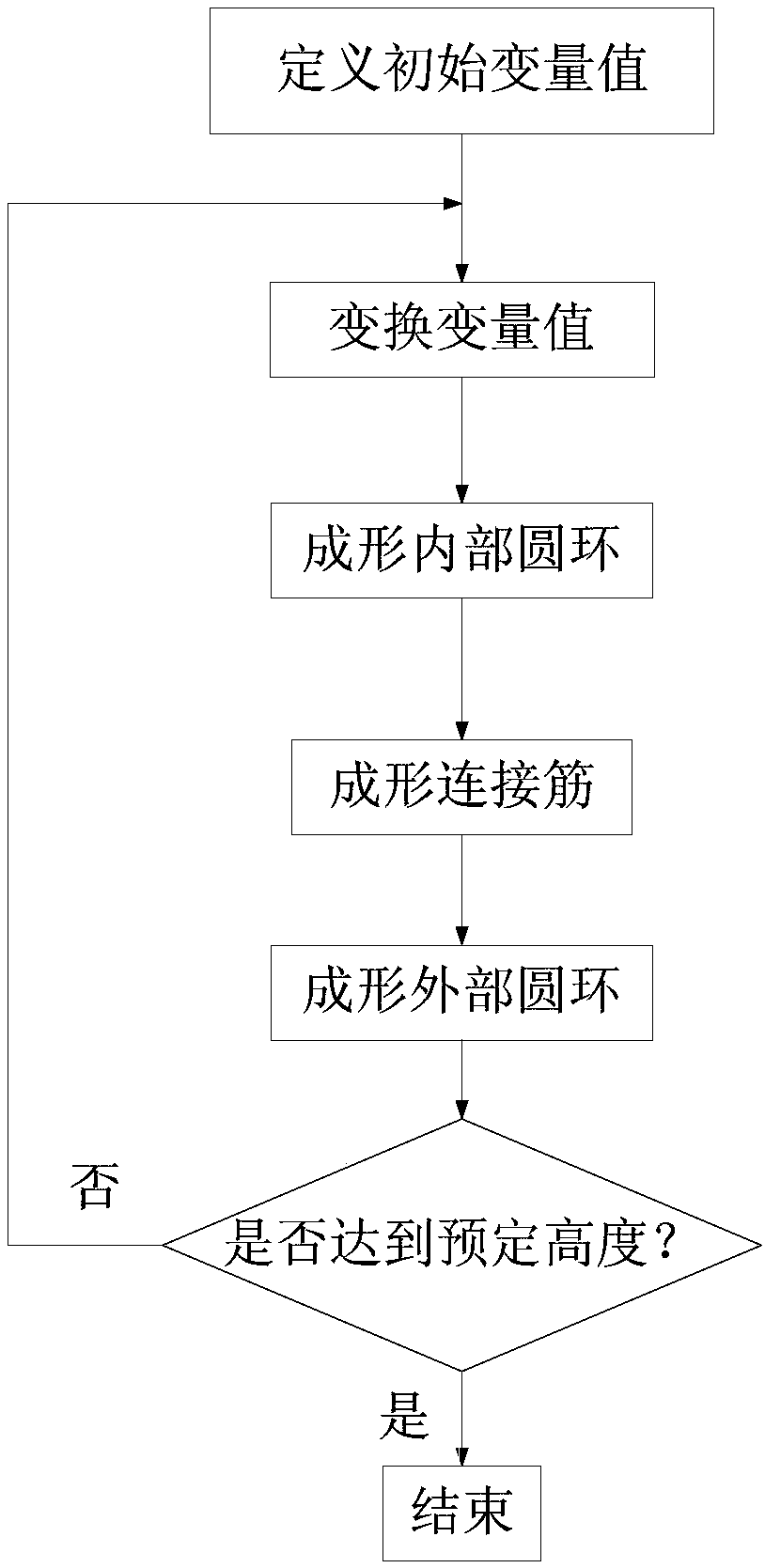
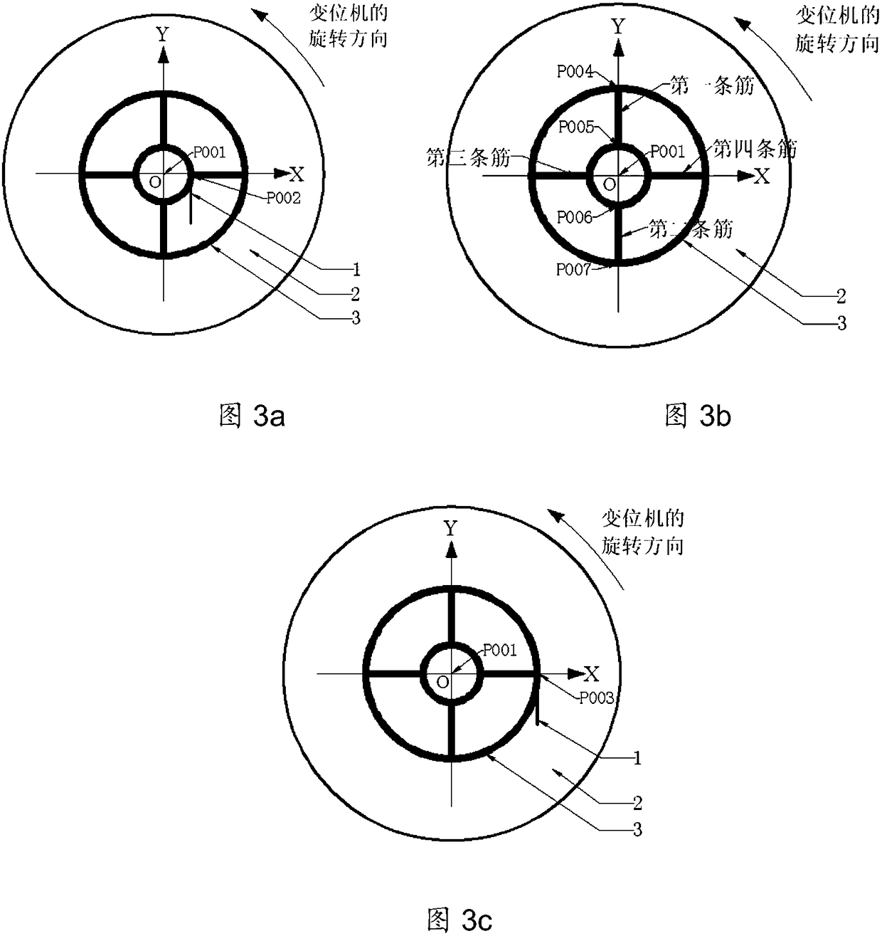

Image

  • Arc fuse additive manufacturing method for a disc-shaped support
  • Arc fuse additive manufacturing method for a disc-shaped support
  • Arc fuse additive manufacturing method for a disc-shaped support

Examples


Embodiment Construction

[0058] Below in conjunction with accompanying drawing and specific embodiment the present invention is described in further detail:

[0059] Such as figure 1 Shown is the structural representation of the disc-shaped support to be prepared in the present invention, wherein figure 1 a is the diagram of 4 connecting bars; figure 1 b is a diagram of 8 connecting ribs; the disc-shaped support is mainly composed of two types of structures, a ring and a connecting rib, wherein the ring has two inner rings and outer rings; the number of connecting ribs is 2n, Every two symmetrical connecting ribs are on the same straight line. The connecting ribs are evenly distributed on the ring, and the angular interval value is α=360° / 2n.

[0060] The forming method of the disc-shaped support in the present invention is divided into a ring forming method and a connecting rib forming method according to its main structural features.

[0061] ① Forming method of the ring: The forming of the ring...


PUM


Abstract

The invention relates to a wire arc additive manufacturing method for a disc-shaped supporting component. The wire arc additive manufacturing method comprises the steps of forming an internal circular ring of the disc-shaped supporting component; forming connecting ribs of the disc-shaped supporting component; forming an external circular ring of the disc-shaped supporting component; and making the internal circular ring, the connecting ribs and the external circular ring of the disc-shaped supporting component reach the required height. According to the wire arc additive manufacturing method for the disc-shaped supporting component, reference coordinate points of the internal circular ring, the external circular ring and the reinforcing ribs in the forming process are obtained through selection of datum points and coordinate transformation; the number of times of searching for demonstration points is greatly reduced; demonstration workload of operators is reduced; product manufacturing efficiency is improved; transportability of a robot program is enhanced; rapid formation of the disc-shaped supporting component manufactured through wire arc additives is achieved; and meanwhile, the wire arc additive manufacturing method with demonstration point searching replaced with coordinate transformation is adopted, disc-shaped supporting components which are different in size and provided with different connecting ribs can be formed, and higher universality is achieved.

Description

technical field [0001] The invention relates to an arc fuse additive manufacturing method for a disc-shaped support member, which belongs to the technical field of additive manufacturing, and is especially suitable for the arc fuse additive manufacturing technical field of a TIG (Tungsten Inert Gas) power supply. Background technique [0002] Wire Arc Additive Manufacture (WAAM) is a method of using the principle of layer-by-layer cladding, using the arc as the heat source, adding wire, and under the control of the program, according to the three-dimensional digital model. -The body is gradually formed into advanced digital manufacturing technology of metal parts. The hardware of the arc fuse additive manufacturing system platform is generally composed of main equipment such as robots, positioners, welding machines, and wire feeders. The control of the main input and output devices by the robot program is realized through the connection of the communication interface. At pr...

Claims


Application Information

Patent Timeline
Patent Type & Authority Patents(China)
IPC IPC(8): B23K9/04B23K9/095
CPCB23K9/044B23K9/0953
Inventor 王国庆田彩兰王福德何京文陈济轮郭晗默严振宇董鹏李权梁晓康刘天亮周庆军
Owner CAPITAL AEROSPACE MACHINERY
Learn More