
Quick tool replacement method for numerical control machine tool and tool magazine

A replacement method, the technology of CNC machine tools, applied in the direction of manufacturing tools, metal processing machine parts, clamping, etc., can solve the problem of long tool change time and so on

Inactive Publication Date: 2017-01-11
BEIJING CTB SERVO CO LTD
View PDF10 Cites 6 Cited by
  • Summary
  • Abstract
  • Description
  • Claims
  • Application Information

AI Technical Summary

Problems solved by technology

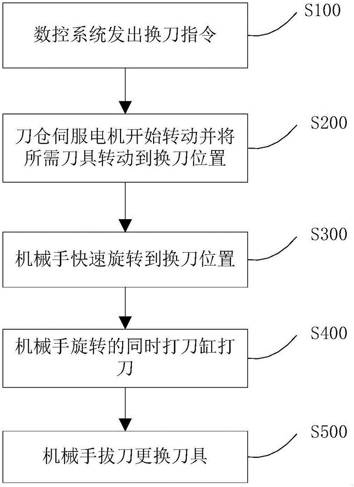
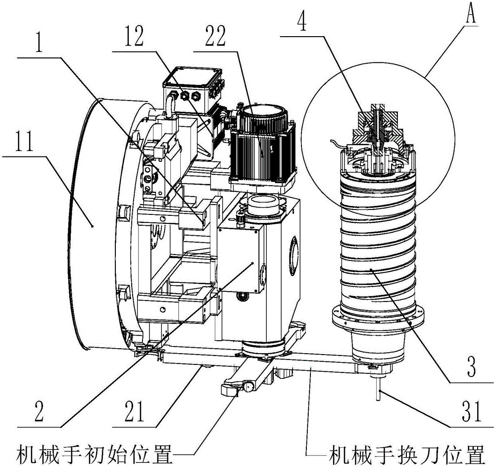
[0004] In order to solve the above-mentioned problems in the prior art, that is, in order to solve the problem that the tool change time between the tool magazine and the electric spindle in the existing CNC machine tool is relatively long, the present invention provides a method for quickly changing tools in a CNC machine tool, which is characterized in that: The method includes the following steps: the numerical control system issues a tool change instruction; the tool magazine servo motor drives the tool magazine to rotate, and rotates the target tool to the tool changing position; the manipulator servo motor drives the manipulator to rotate, and rotates the manipulator to the position of the tool to be replaced; When the manipulator rotates, the knife cylinder starts to strike the knife; the manipulator performs tool change

Method used


Image

  • Quick tool replacement method for numerical control machine tool and tool magazine
  • Quick tool replacement method for numerical control machine tool and tool magazine
  • Quick tool replacement method for numerical control machine tool and tool magazine

Examples


Embodiment Construction

[0016] Preferred embodiments of the present invention are described below with reference to the accompanying drawings. Those skilled in the art should understand that these embodiments are only used to explain the technical principles of the present invention, and are not intended to limit the protection scope of the present invention. For example, although the components in the drawings are drawn according to a certain positional relationship, this positional relationship is not static, and those skilled in the art can make adjustments to suit specific applications.

[0017] It should be noted that, in the description of the present invention, the terms "center", "upper", "lower", "left", "right", "vertical", "horizontal", "inner", "outer" etc. The terms of the indicated direction or positional relationship are based on the direction or positional relationship shown in the drawings, which are only for the convenience of description, and do not indicate or imply that the devic...


PUM


Abstract

The invention belongs to the field of numerical control machine tools, particularly provides a quick tool replacement method for a numerical control machine tool and a tool magazine, and aims to solve the problem of excessively long tool replacement time between a tool magazine and an electro-spindle of a conventional numerical control machine tool. The quick tool replacement method comprises the following steps: a numerical control system gives a tool replacement command; a tool chamber servomotor drives a tool chamber to rotate and to rotate a target tool to a tool replacement position; a manipulator servomotor drives a manipulator to quickly rotate to the position of a to-be-replaced tool; a tool striking cylinder starts to strike tools while the manipulator rotates, and the tool striking cylinder just finishes the tool striking action when the manipulator holds a tool on an electro-spindle; and the manipulator conducts tool replacement. Furthermore, encoders are used for accurately positioning all the tools on the tool chamber and the manipulator. The quick tool replacement method for the numerical control machine tool can not only prevent the tools from falling and being disordered, but also improve the tool replacement speed.

Description

technical field [0001] The invention belongs to the field of numerical control machine tools, and specifically provides a method for quickly replacing a tool of a numerical control machine tool and a tool magazine. Background technique [0002] At present, the tool magazine is installed with a reducer through an asynchronous motor, and then drives the cam structure to change the tool. The tool change process between the tool magazine and the electric spindle is determined by multiple proximity switches and information feedback. Due to the positioning accuracy of the proximity switch The speed of the asynchronous motor is not high, and the speed of the asynchronous motor is uncontrollable, which makes the tool change time longer. In addition, since the hydraulic tooling cylinder provides hydraulic oil and pressure through the hydraulic pump, the hydraulic loading process takes a certain amount of time, thereby increasing the tool changing time. [0003] Correspondingly, ther...

Claims


Application Information

Patent Timeline
IPC IPC(8): B23Q3/155B23Q3/157
CPCB23Q3/155B23Q3/1552B23Q3/157B23Q3/15713B23Q3/1572
Inventor 项久鹏郭志
Owner BEIJING CTB SERVO CO LTD
Learn More