
Four-drive two-face chip polishing machine

A technology for polishing machines and wafers, which is applied in the direction of grinding racks, grinding machine parts, grinding/polishing equipment, etc., and can solve problems such as imperfect design of wafer grinding machines and insufficient production efficiency.

Active Publication Date: 2017-01-11
YUNNAN CRYSTALAND
View PDF7 Cites 10 Cited by
  • Summary
  • Abstract
  • Description
  • Claims
  • Application Information

AI Technical Summary

Problems solved by technology

[0005] The purpose of the present invention is to provide a four-drive double-sided wafer grinder, which solves the problems in the prior art that the design of the dual-track drive wafer grinder is not perfect and the production efficiency has not been fully utilized.

Method used


Image

  • Four-drive two-face chip polishing machine
  • Four-drive two-face chip polishing machine

Examples


Embodiment Construction

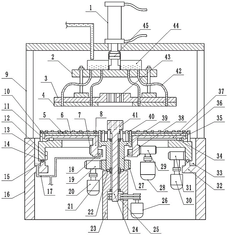
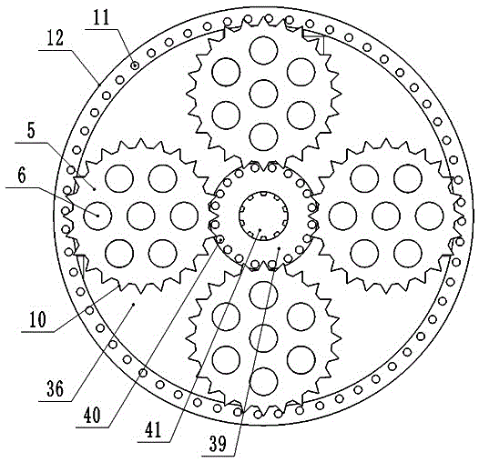
[0009] Examples such as figure 1 and figure 2 Shown: a four-wheel-drive double-sided wafer grinder, the double-sided grinder is composed of a lower grinding device and an upper grinding device, the lower grinding device is installed in the chassis, the upper grinding device is installed on the frame 9, and the frame 9 Installed on the chassis 16, the cylinder 1 of the upper grinding device is vertically installed on the crossbeam of the frame 9, the end of the piston rod of the cylinder 1 is equipped with a connecting plate 2, and a pressure plate 3 is installed below the connecting plate 2, and the pressure plate 3 is lowered. An upper grinding disc 4 is installed, a grinding liquid tank 44 is installed on the connecting plate 2, and a grinding liquid delivery pipe 42 is installed on the pressure plate 3; a linkage hole 43 is processed in the middle of the pressure plate 3, and a rack is processed in the linkage hole 43 , the piston rod end of the cylinder 1 is fixedly inst...


PUM


Abstract

The invention relates to a four-drive two-face chip polishing machine. The four-drive two-face chip polishing machine is formed by a lower polishing device and an upper polishing device; a pressure disc and an upper polishing disc are installed below an air cylinder of the upper polishing device through rotation connectors, and a linkage hole is machined in the middle of the pressure disc; a first transmission column is installed on an outer rotary disc of the lower polishing device, a lower polishing disc is installed on a lower tray, a second transmission column is installed on an inner rotary disc, and a connector is installed on a linkage shaft; and the first transmission column, the lower polishing disc, the second transmission column and the connector are driven by a first motor, a second motor, a third motor and a fourth motor correspondingly; the pressure disc is driven by the connector on the linkage shaft, a chip containing hole is machined in a chip positioning liner, the chip positioning liner is placed on the lower polishing disc, and side teeth of the chip positioning liner are combined with the first transmission column and the second transmission column in a clamped manner. By means of the technology, the first transmission column and the second transmission column drive the chip positioning liner to rotate between the upper polishing disc and the lower polishing disc in two directions, and chips are polished for the first time; and meanwhile, when the upper polishing disc and the lower polishing disc rotate, the chips are polished for the second time, work of polishing at the two times are overlapped, and therefore the polishing efficiency of the chips is increased in a multiplied manner.

Description

technical field [0001] The technology belongs to the technical field of wafer rough polishing equipment, and in particular relates to a four-drive double-sided wafer polisher. Background technique [0002] After the sapphire wafer is cut piece by piece from the ingot, there will be rough cutting marks on the cut surface, so the wafer needs to be ground and polished. In the prior art, the technology used for wafer polishing is the closest to the present invention is the patent "Dual-track Driven Wafer Grinding Machine" invented by our company, patent application number: CN201520936550.4, the dual-track driven wafer grinding machine The support frame of the machine is equipped with a fixed disc, the upper surface of the fixed disc is installed with a circular lower grinding disc, the center of the fixed disc is installed with a central rotating shaft, the lower part of the central rotating shaft is connected to the central drive motor through a transmission gear, and the upper...

Claims


Application Information

Patent Timeline
IPC IPC(8): B24B7/22B24B41/02B24B41/00
CPCB24B7/226B24B7/228B24B41/00B24B41/02
Inventor 吴康王庆刘云波
Owner YUNNAN CRYSTALAND
Learn More