Clamping device with tilting prevention function
A clamping device and anti-tilt technology, applied in the direction of manufacturing tools, vices, etc., can solve the problems of uneven processing force, poor stability of the clamping tool, easy to tilt, etc., to prolong the service life and avoid the workpiece. Surface scratches and deformation, the effect of ensuring accuracy
- Summary
- Abstract
- Description
- Claims
- Application Information
AI Technical Summary
Problems solved by technology
Method used
Image

Examples
Embodiment 1
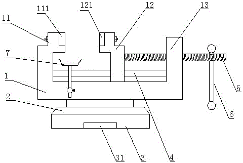
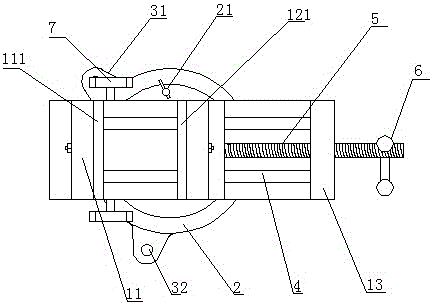
[0023] combined with Figure 1-2 As shown, a clamping device with an anti-tilt function includes a body 1, a rotating table 2, a base 3, a static half tong 11, a moving half tong 12, a threaded rod 5 and a handle 6, a body 1, a rotating table 2 and a base 3 are connected sequentially from top to bottom and the rotating table 2 can rotate on the base 3, the static half tongs 11 are installed on the body 1 and connected to one end of the body 1 integrally, the moving half tongs 12 and the static half tongs The pliers 11 are relatively arranged on the body 1, and the other end of the body 1 away from the static half pliers 11 is provided with a boss 13, and the boss 13 is threadedly connected with a threaded rod 5, and one end of the threaded rod 5 is connected to the movable half. The other end of the pliers 12 is connected with a handle 6, and a bracket 7 is arranged on both sides of the body 1 in the length direction, and the bracket 7 is located directly below the clamping su...
Embodiment 2
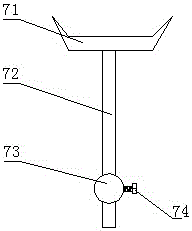
[0027] In order to further realize the adjustment of the bracket 7, on the basis of Embodiment 1, combined with the attached Figure 1-3 As shown, the bracket 7 includes a tray 71, a telescopic rod 72 connected to the lower end of the tray 71, the telescopic rod 72 is slidably connected with a bracket 73 installed on the body 1 and the bracket 73 is also provided with a bracket for fixing the The locking screw 74 of the telescoping rod 72 and the relative position of the support 73.
[0028] working principle:
[0029] First, loosen the locking screw 74, move the telescopic rod 72 down to the lowest point, and install the workpiece to be processed on the moving half tong 12 and the static half of the present invention according to the steps of installing the workpiece described in the working principle in Embodiment 1. Tighten between the pliers 11, adjust the telescopic rod 72 upwards until the upper surface of the tray 71 is firmly against the workpiece, and tighten the loc...
Embodiment 3
[0032] In order to further improve the stability and convenience of operation of the present invention, on the basis of any one of the above embodiments, in combination with the attached Figure 1-3 As shown, a slide bar 4 is arranged between the static half tong 11 and the boss 13, the axis of the slide bar 4 is arranged parallel to the axis of the threaded rod 5, and the slide bar 4 runs through the movable half tong 12, The movable half tong 12 can slide back and forth along the slide bar 4 .
[0033] In this embodiment, the number of the sliding rods 4 is two.
[0034] In this embodiment, the clamping surface of the movable half pliers 12 is equipped with a dynamic contact block 121 through bolts, and the clamping surface of the static half pliers 11 is equipped with a static contact block 111 through bolts, and the dynamic contact block 121 and the static contact The material of block 111 is the same.
[0035] In this embodiment, the materials of the moving contact bloc...
PUM
 Abstract
Description
Claims
Application Information
 - R&D
- Intellectual Property
- Life Sciences
- Materials
- Tech Scout
- Unparalleled Data Quality
- Higher Quality Content
- 60% Fewer Hallucinations
Browse by: Latest US Patents, China's latest patents, Technical Efficacy Thesaurus, Application Domain, Technology Topic, Popular Technical Reports.
© 2025 PatSnap. All rights reserved.Legal|Privacy policy|Modern Slavery Act Transparency Statement|Sitemap|About US| Contact US: help@patsnap.com