
Robot product shell manufacturing method adopting nitrogen forming

A manufacturing method and robot technology, applied in the field of robot product manufacturing and processing, can solve problems such as increasing process costs, achieve the effects of optimizing product process, increasing strength and dimensional stability, and improving product yield

Inactive Publication Date: 2017-01-11
SHANGHAI XPARTNER ROBOTICS
View PDF5 Cites 0 Cited by
  • Summary
  • Abstract
  • Description
  • Claims
  • Application Information

AI Technical Summary

Problems solved by technology

The screw column of the robot product shell is generally ejected by the cylinder column first, and the copper nut is used for secondary processing by heat-melting process, which increases the process cost

Method used


Image

  • Robot product shell manufacturing method adopting nitrogen forming
  • Robot product shell manufacturing method adopting nitrogen forming
  • Robot product shell manufacturing method adopting nitrogen forming

Examples


Embodiment Construction

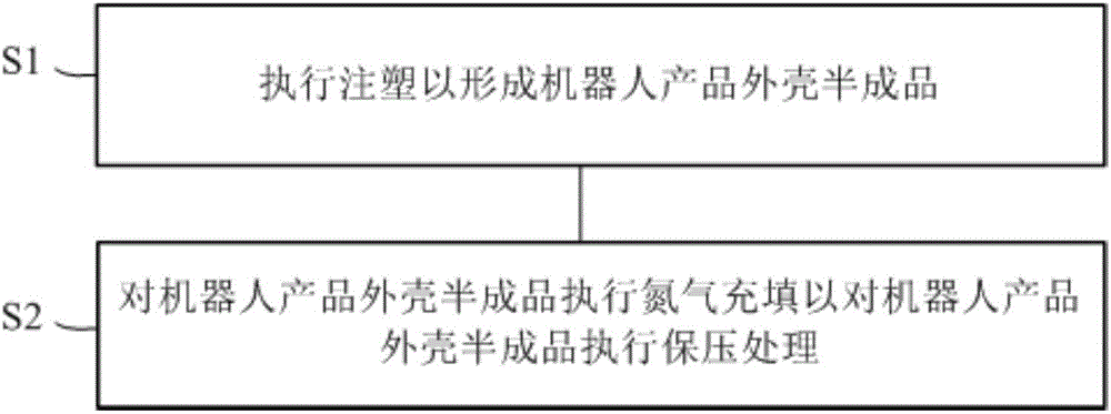
[0018] figure 2 It is a flow chart of a method for manufacturing a robot product shell using nitrogen forming according to a preferred embodiment of the present invention.

[0019] Such as figure 2 As shown, the manufacturing method of the robot product shell adopting nitrogen forming according to the preferred embodiment of the present invention comprises:

[0020] First step S1: performing injection molding to form a semi-finished robot product shell;

[0021] Second step S2: Nitrogen filling is performed on the semi-finished product casing of the robot product to perform pressure-holding treatment on the semi-finished product casing of the robot product.

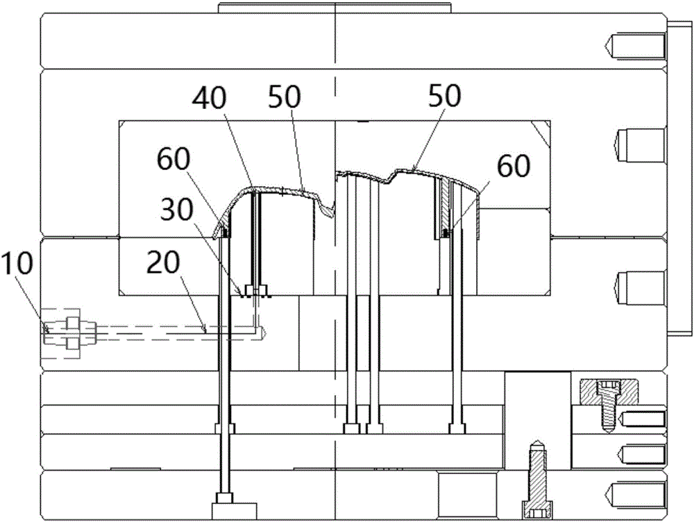
[0022] Specifically, such as image 3 As shown, in the second step S2, in the nitrogen filling equipment, the nitrogen connector 10 is connected to the nitrogen hole 20, the nitrogen hole 20 is connected to the nitrogen needle 40 through the O-ring 30, and the nitrogen needle 40 is pierced into the shell of the robot...


PUM


Abstract

The invention discloses a robot product shell manufacturing method adopting nitrogen forming. The method comprises the following steps: (1) the injection molding is performed to form a robot product shell semi-finished product; and (2) the robot product shell semi-finished product is filled with nitrogen to perform the pressure keeping treatment for the robot product shell semi-finished product. In the step (2), in nitrogen filling equipment, a nitrogen joint is connected to a nitrogen hole; the nitrogen hole is connected to a nitrogen needle by an O-shaped ring; the nitrogen needle is inserted in a nitrogen way of the robot product shell semi-finished product; and nitrogen is filled in the nitrogen joint, so that the nitrogen enters the nitrogen way of the robot product shell semi-finished product to perform the pressure keeping treatment for the robot product shell semi-finished product.

Description

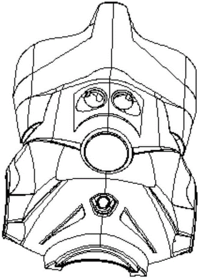
technical field [0001] The invention relates to the field of manufacturing and processing of robot products, in particular to a method for manufacturing robot product shells formed by nitrogen gas. Background technique [0002] Currently, in robot product shells (such as figure 1 In the manufacturing process of the shown robot product shell), the thickness of the ribs is generally reduced, so that the thickness of the ribs is not greater than 0.5T, and the shape will not be easy to fill at this time. In the case that the appearance thickness is only 1.5MM, and the thickness of the rib is also 1.5MM, the surface of the robot product shell will shrink. [0003] On the other hand, when the screw column needs to be injected with an insert copper nut, the top surface is thicker. The screw column of the robot product shell is generally ejected by the cylinder column first, and the copper nut is used for secondary processing by heat-melting process, which increases the process co...

Claims


Application Information

Patent Timeline
Patent Type & Authority Applications(China)
IPC IPC(8): B29C45/57
CPCB29C45/0025B29C45/174
Inventor 恽为民於琴年庞作伟
Owner SHANGHAI XPARTNER ROBOTICS
Learn More