

Belt guiding and conveying device for pipe baling of automatic rolling machine
A technology of winding machine and strapping belt, which is applied in the direction of bundling materials, etc., to achieve the effect of fast speed, high bundling degree and simple overall structure
- Summary
- Abstract
- Description
- Claims
- Application Information
AI Technical Summary
Problems solved by technology
Method used
Image

Examples
Embodiment 1
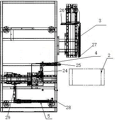
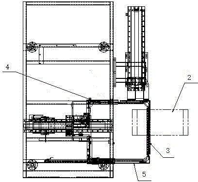
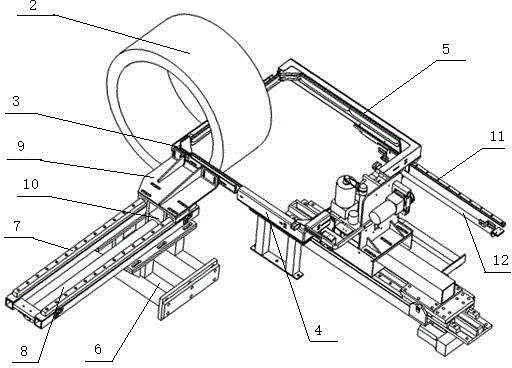
[0032] Such as Figure 1 to Figure 8 Shown, a kind of guide belt feeding device that is used for automatic winder pipe packing, comprises frame 1, and the guide belt frame that can let packing belt pass through is set on said frame, and described belt guide frame is in When the bale is in operation, the shape is a square closed-loop structure, and the square closed-loop structure can pass through the pipe 2 wound on the take-up reel, so that the part of the pipe to be baled is located in the closed-loop structure.
[0033] The belt guide frame includes three beltway components arranged on the frame and having an L-shaped overall structure, the beltway components can be used for the straps to pass through, and the beltway components include a fixedly installed first beltway component 4. A slidable second beltway assembly 3 and a slidable third beltway assembly 5; the first beltway assembly 4 is fixed on the frame 1, and the second beltway assembly 3 is set by the first sliding ...
PUM
 Abstract
Description
Claims
Application Information