Eureka AIR delivers breakthrough ideas for toughest innovation challenges, trusted by R&D personnel around the world.

Automatic feed and discharge mechanism for PC component stacking machine bench

The technology of stacker and die table is applied in the field of automatic in-out mechanism of stacker die table, which can solve the problems of complex structure, low stability and low work efficiency, and achieve the effects of high transmission efficiency, stable operation and simple structure.

Inactive Publication Date: 2017-01-11
JIANGSU UNIV OF SCI & TECH
View PDF5 Cites 4 Cited by
  • Summary
  • Abstract
  • Description
  • Claims
  • Application Information

AI Technical Summary

Problems solved by technology

The automatic entry and exit mechanism of the mold table of the PC component stacker is an important part of the stacker. Its main function is to take and deliver the mold table quickly, stably and accurately. The working efficiency of the entry and exit mechanism directly affects the working efficiency of the entire stacker. Affect the production efficiency of the whole production line
Most of the entry and exit mechanisms of existing stackers are purely mechanical structures. The rotary motion of the rotating shaft is driven by gears or chains. The linear motion of the mold table is driven by rack and pinion. The disadvantage is that the structure Complex, heavy, low stability, low work efficiency

Method used


Image

  • Automatic feed and discharge mechanism for PC component stacking machine bench
  • Automatic feed and discharge mechanism for PC component stacking machine bench
  • Automatic feed and discharge mechanism for PC component stacking machine bench

Examples


Embodiment Construction

[0018] In order to make the purpose, technical solution and advantages of the present invention more clear, the present invention will be further described in detail below in conjunction with the accompanying drawings and embodiments. It should be understood that the specific embodiments described here are only used to explain the present invention, not to limit the present invention.

[0019] The directional terms mentioned in the present invention, such as "up", "down", "front", "back", "left", "right", etc., are only referring to the directions of the drawings. Therefore, the use of directional terms is used to illustrate and understand the present invention, but not to limit the present invention.

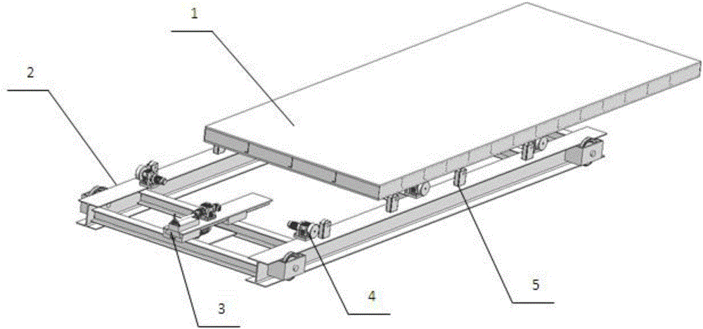
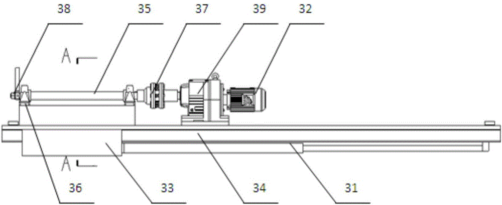
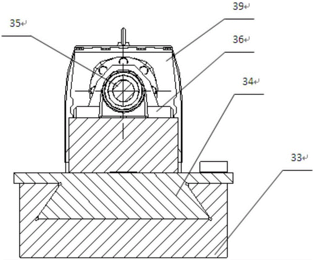
[0020] Such as Figure 1 to Figure 4 As shown, it is an automatic entry and exit mechanism for a PC component stacker mold platform of the present invention, including a stacker bracket 2 connected to the stacker, and symmetrical intervals are arranged on the front and rear fr...


PUM


Abstract

An automatic feed and discharge mechanism for a PC component stacking machine bench comprises a stacking machine bracket connected with a stacking machine. Friction wheels and supporting wheels are symmetrically arranged on a front frame and a rear frame of the stacking machine bracket at intervals. The stacking machine execution bench is installed on the friction wheels and the supporting wheels. A bench taking and feeding mechanism fixedly connected with the stacking machine bracket is arranged at the two ends between the stacking machine bracket and the stacking machine execution bench in a mirror image manner. The bench taking and feeding mechanism comprises an installation plate. The installation plate is fixedly connected with the stacking machine bracket and is provided with a dovetail groove. A slide block matched with the dovetail groove is arranged on the installation plate. A speed reducer and a bearing pedestal are sequentially arranged on the slide block from right to left in an isolated manner. The right side of the speed reducer is connected with a motor. The left side of the speed reducer is connected with a coupling. The coupling is connected with one end of a rotating shaft. The other end of the rotating shaft penetrates a bearing pedestal and is connected with a bench hook connected with the stacking machine execution bench in a hooking manner. A hydraulic cylinder is further fixedly connected with the right end of the installation plate. The other end of the hydraulic cylinder is connected with the slide block. The mechanism has the beneficial effects of being simple in structure, small in weight, stable in running and high in transmission efficiency.

Description

technical field [0001] The invention relates to an automatic entry and exit mechanism for a mold table of a stacker in the technical field of an automatic production line of concrete prefabricated components, and is specifically used for realizing automatic entry and exit of a mold table on a stacker machine into and out of a curing kiln. Background technique [0002] The PC component stacker is connected to the production line and the curing kiln. Through automatic control, the stacker receives the rough boards to be cured on the production line and transports them to the curing kiln for maintenance. Therefore, the working efficiency, stability and automation of the stacker are of great importance to the entire PC. Component automation production lines are crucial. The automatic entry and exit mechanism of the mold table of the PC component stacker is an important part of the stacker. Its main function is to take and deliver the mold table quickly, stably and accurately. Th...

Claims


Application Information

Patent Timeline
Patent Type & Authority Applications(China)
IPC IPC(8): B65G57/00
CPCB65G57/00
Inventor 张礼华顾振鹏刘芳华曾晓文
Owner JIANGSU UNIV OF SCI & TECH
Why Eureka
Eureka Blog
Learn More