Engine air intake system wavelength pipe and engine air intake manifold

A technology of air intake system and intake manifold, which is applied in the direction of engine components, machines/engines, and charging systems, which can solve problems such as high adjustment costs, reduced product competitiveness, and limited space, and achieve the elimination of sound waves of different frequencies , Reduce manufacturing costs, reduce the effect of research and development costs

Inactive Publication Date: 2017-01-11
ANHUI JIANGHUAI AUTOMOBILE GRP CORP LTD
View PDF7 Cites 1 Cited by
  • Summary
  • Abstract
  • Description
  • Claims
  • Application Information

AI Technical Summary

Problems solved by technology

Since the wavelength tube is arranged on the air intake pipeline, the air intake pipeline is located in the engine compartment of the car. In addition to the intake pipeline, there are also many components such as the engine, air filter, battery, water tank replenishment tank, and relay box in the engine compartment. Limited, difficult to arrange
In addition, after arranging more wavelength tubes, the casting difficulty and cost of the intake tube will be increased. The increase in casting difficulty will reduce the product qualification rate and cause risks to product quality. The increase in cost will lead to a decline in product competitiveness and affect corporate benefits.
In addition, when the same engine is matched with different models, the noise of the intake system will also change due to the difference in pipeline layout and boundaries. Therefore, it is necessary to adjust the parameters of the wavelength tube, which is expensive to adjust and takes a long time to develop.

Method used


Image

  • Engine air intake system wavelength pipe and engine air intake manifold
  • Engine air intake system wavelength pipe and engine air intake manifold
  • Engine air intake system wavelength pipe and engine air intake manifold

Examples


Embodiment Construction

[0030] Embodiments of the present invention are described in detail below, examples of which are shown in the drawings, wherein the same or similar reference numerals designate the same or similar elements or elements having the same or similar functions throughout. The embodiments described below by referring to the figures are exemplary only for explaining the present invention and should not be construed as limiting the present invention.

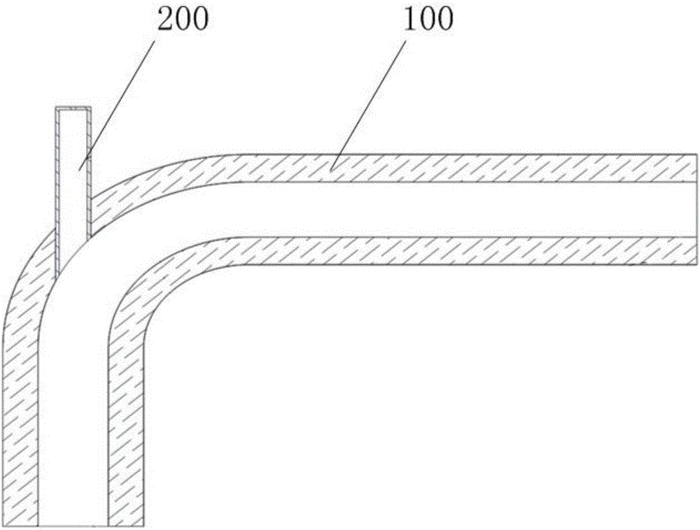
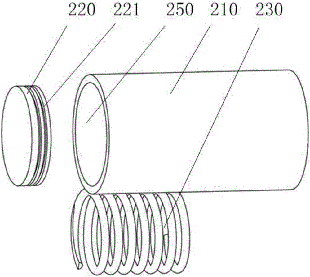
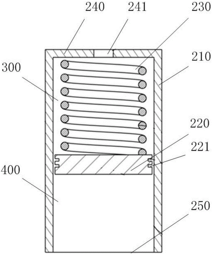
[0031] figure 1 A cross-sectional view of the engine intake system wavelength tube assembled to the engine intake pipe provided by the embodiment of the present invention, figure 2 An exploded schematic view of the wavelength tube of the engine intake system provided by the embodiment of the present invention, image 3 A cross-sectional view of the wavelength tube of the engine intake system provided by the embodiment of the present invention.

[0032] An embodiment of the present invention provides a wavelength tube for an engine int...


PUM


Abstract

The invention discloses an engine air intake system wavelength pipe and an engine air intake manifold. The wavelength pipe comprises a pipe body, a plunger and a spring. The pipe body is arranged on an air intake pipe of an engine, one end of the pipe body communicates with the air intake pipe, and a cover plate is arranged at the other end of the pipe body. The plunger is arranged in the pipe body in a sliding manner, and an air cavity is formed between the plunger and the cover plate. The spring is arranged in the air cavity, one end of the spring abuts against the cover plate, and the other end of the spring abuts against the plunger. According to the engine air intake system wavelength pipe and the engine air intake manifold, the plunger and the spring are arranged in the pipe body, a reflection cavity is formed between the plunger and the air intake end of the pipe body accordingly, the length of the reflection cavity can be adjusted under the situation that the wavelength pipe is not replaced, sound waves different in frequency are removed accordingly, meanwhile, the number of wavelength pipes in an existing engine system is reduced, and the manufacturing cost of the wavelength pipe is reduced.

Description

technical field [0001] The invention relates to the technical field of engines, in particular to an engine intake system wavelength tube and an engine intake manifold. Background technique [0002] Automobiles powered by internal combustion engines have been developed for more than 100 years and have had a profound impact on the development and progress of human society. People use the power provided by internal combustion engines for material production and wealth creation. The internal combustion engine uses the chemical energy of fuel to generate mechanical kinetic energy. During this process, it is necessary to continuously deliver fuel to the engine, and at the same time, continuously distribute fresh air to the engine, and at the same time, discharge combustion exhaust gas. In the intake and exhaust stages of the engine, due to the periodic pressure pulsation of the gas and the existence of gas column resonance in the pipeline, noise is generated in the intake pipeline...

Claims


Application Information

Patent Timeline
Patent Type & Authority Applications(China)
IPC IPC(8): F02M35/104
CPCF02M35/10091F02M35/104
Inventor 王强杨林强王军胡昌良张超孙影卓丽颖张军瑞雷蕾李波路明
Owner ANHUI JIANGHUAI AUTOMOBILE GRP CORP LTD
Why Eureka
Try Eureka