
High-frequency vibration distributed optical fiber sensing system based on random sampling

A distributed optical fiber and high-frequency vibration technology, which is applied to instruments, measuring devices, and wave/particle radiation, etc., can solve the problem of narrow vibration frequency response range, achieve the effect of widening the frequency response range and increasing system cost

Active Publication Date: 2017-01-11
CHONGQING UNIV +1
View PDF9 Cites 12 Cited by
  • Summary
  • Abstract
  • Description
  • Claims
  • Application Information

AI Technical Summary

Problems solved by technology

[0003] In the prior art, the optical fiber vibration distributed sensing system generally uses a uniform sampling method to sample vibration events. Since the sampling rate in the system is limited by the round-trip time of pulsed light, the vibration frequency response range of the system is often limited to low frequencies, and the transmission The longer the sensing distance, the narrower the vibration frequency response range of the system

Method used


Image

  • High-frequency vibration distributed optical fiber sensing system based on random sampling
  • High-frequency vibration distributed optical fiber sensing system based on random sampling
  • High-frequency vibration distributed optical fiber sensing system based on random sampling

Examples


Embodiment Construction

[0020] The following will clearly and completely describe the technical solutions in the embodiments of the present invention with reference to the accompanying drawings in the embodiments of the present invention. Obviously, the described embodiments are only some, not all, embodiments of the present invention. Based on the embodiments of the present invention, all other embodiments obtained by persons of ordinary skill in the art without making creative efforts belong to the protection scope of the present invention.

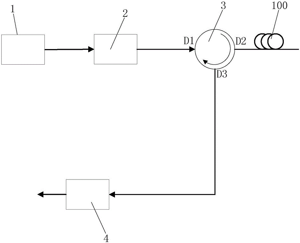
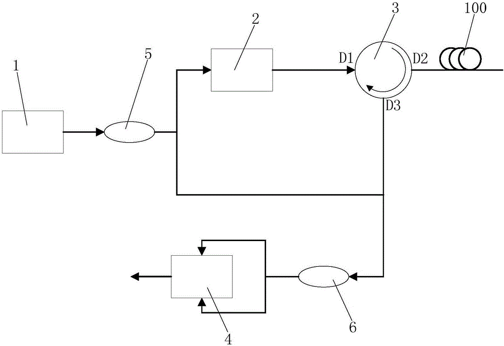
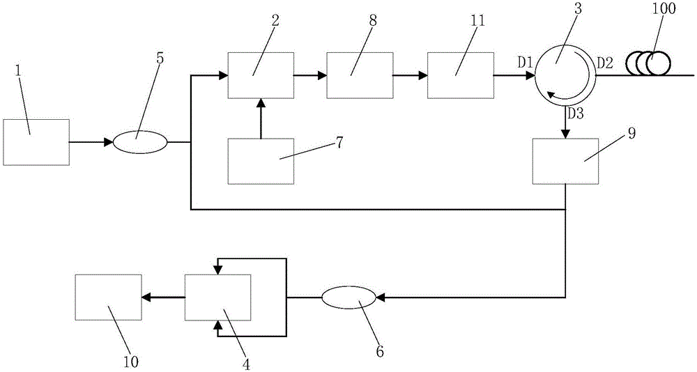
[0021] refer to figure 1 , is a schematic structural diagram of the first embodiment of the high-frequency vibration distributed optical fiber sensing system based on random sampling in the present invention. The high-frequency vibration distributed optical fiber sensing system of the embodiment of the present invention includes a laser 1 , an intensity modulator 2 , a circulator 3 and a detector 4 .

[0022] The laser 1 is connected to the intensity modulato...


PUM


Abstract

The invention discloses a high-frequency vibration distributed optical fiber sensing system based on random sampling. The system comprises a laser device, an intensity modulator, a circulator and a detector. The laser device is used for producing continuous laser signals. The intensity modulator is used for receiving the laser signals and modulating the laser signals into random pulsed light. The first end of the circulator is used for receiving the random pulsed light, the second end of the circulator is used for injecting the random pulsed light into a sensing optical fiber and receiving Rayleigh scattering light transmitted reversely in the sensing optical fiber, and the third end of the circulator is sued for outputting the Rayleigh scattering light. The detector is used for converting the Rayleigh scattering light into electric signals. The system can greatly widen the frequency response range, the vibration frequency response range is not limited by sensing distance, high-frequency vibration is facilitated, and particularly wide-spectrum vibration with the frequency sparse characteristic is effectively detected.

Description

technical field [0001] The invention relates to the field of optical fiber sensing, in particular to a high-frequency vibration distributed optical fiber sensing system based on random sampling. Background technique [0002] In the health monitoring and diagnosis of major projects and infrastructures such as large-scale building structures, aerospace, petrochemical, and power systems, optical fiber sensing technology has gradually gained popularity due to its small sensitive components, high durability, absolute measurement, and distributed monitoring. It is a trend to replace electrical sensors as the preferred sensitive components for sensor health monitoring. Among them, the technical research and application of distributed monitoring of vibration over long distances using optical fibers is continuously deepening. [0003] In the prior art, the optical fiber vibration distributed sensing system generally uses a uniform sampling method to sample vibration events. Since th...

Claims


Application Information

Patent Timeline
IPC IPC(8): G01H9/00
CPCG01H9/006
Inventor 朱涛张敬栋
Owner CHONGQING UNIV
Learn More