

Charging current limiting device and method for battery of energy storage system
A battery charging and energy storage system technology, applied in the field of energy storage systems, can solve the problems affecting the service life of the battery system, the internal resistance of the battery cells, and the internal resistance of parallel battery strings. The effect of battery performance
- Summary
- Abstract
- Description
- Claims
- Application Information
AI Technical Summary
Problems solved by technology
Method used
Image

Examples
Embodiment 1
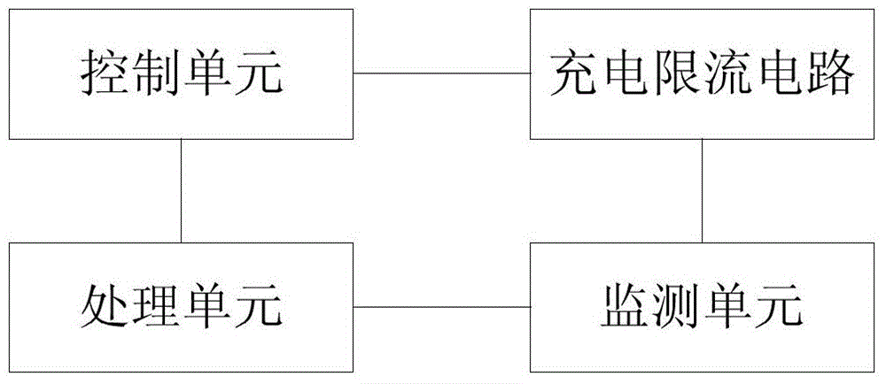
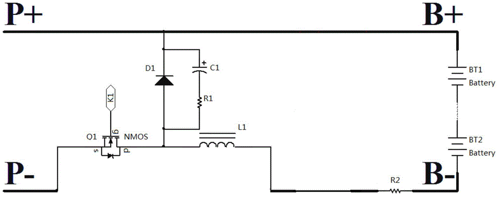
[0035] see figure 1 and figure 2 shown.
[0036] The present invention provides a battery charging current limiting device for an energy storage system, which includes a control unit, a charging current limiting circuit, a monitoring unit, and a processing unit. The charging current limiting circuit includes a first field effect transistor Q1, an inductor L1, a capacitor C1, Freewheeling diode D1, first resistor R1 and sampling resistor R2; the gate G of the first field effect transistor Q1 is connected to the control unit, the source S of the first field effect transistor Q1 is connected to the negative pole of the power supply, and the The drain D of the first field effect transistor Q1 is connected to the first end of the inductor L1, the second end of the inductor L1 is connected to one end of the sampling resistor R2, and the other end of the sampling resistor R2 is connected to the negative side of the battery string. connection; the capacitor C1 is connected in seri...
Embodiment 2
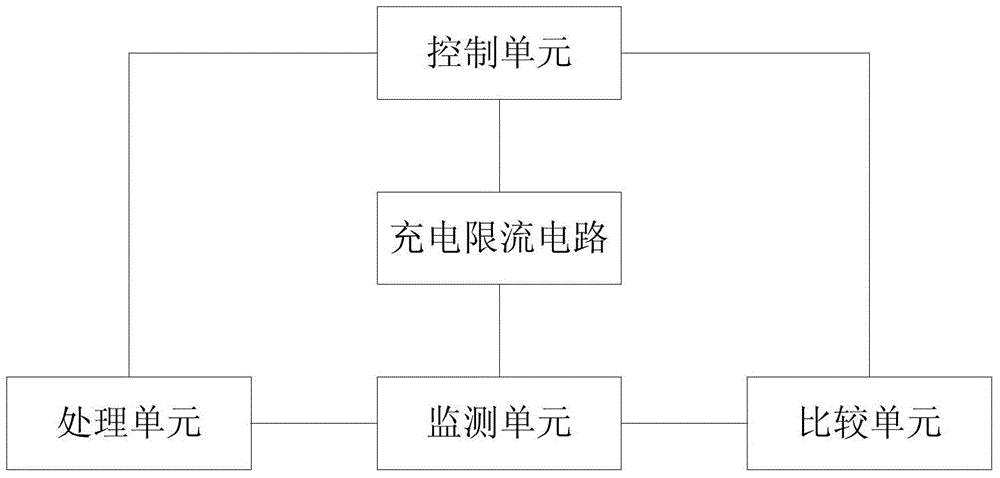
[0046] see image 3 and Figure 4 shown.
[0047] The present invention provides a battery charging current limiting device for an energy storage system, which includes a control unit, a charging current limiting circuit, a monitoring unit, and a processing unit. The charging current limiting circuit includes a first field effect transistor Q1 and a third field effect transistor Q3 , inductor L1, capacitor C1, freewheeling diode D1, first resistor R1 and sampling resistor R2; the gate G of the first field effect transistor Q1 is connected to the control unit, and the source S of the first field effect transistor Q1 connected to the negative pole of the power supply, the drain D of the first field effect transistor Q1 is connected to the first end of the inductor L1, and the second end of the inductor L1 is connected to the source S of the third field effect transistor Q3, so The drain D of the third field effect transistor Q3 is connected to one end of the sampling resistor ...
Embodiment 3
[0056] see image 3 and Figure 5 shown.
[0057] The present invention provides a battery charging current limiting device for an energy storage system, including a control unit, a charging current limiting circuit, a monitoring unit, and a processing unit. The charging current limiting circuit includes a first field effect transistor Q1 and a second field effect transistor Q2 , the third field effect transistor Q3, inductor L1, capacitor C1, freewheeling diode D1, first resistor R1 and sampling resistor R2; the gate G of the first field effect transistor Q1 is connected to the control unit, and the first field effect transistor The source S of the effect transistor Q1 is connected to the negative pole of the power supply, the drain D of the first field effect transistor Q1 is connected to the first end of the inductor L1, and the second end of the inductor L1 is connected to the third field effect transistor Q3 The source S of the third field effect transistor Q3 is connec...
PUM
 Abstract
Description
Claims
Application Information