Control method and control circuit of switching circuit, and switching circuit apparatus

A switching circuit and control circuit technology, which is applied in the field of circuits, can solve the problems that the duty cycle of the conduction signal TON' cannot be continuously reduced, and the load current of the switching circuit cannot be reduced, etc.

Active Publication Date: 2017-01-11
JOULWATT TECH ZHANGJIAGANG INC LTD
View PDF5 Cites 2 Cited by
  • Summary
  • Abstract
  • Description
  • Claims
  • Application Information

AI Technical Summary

Problems solved by technology

[0004] However, the inventors of the present application have found that after the switch circuit enters DCM from CCM, as the load decreases, the load current will decrease, and the conduction time of the first switch tube 1' will be shortened. It can be seen from the working process that the period of the conduction signal TON' of the first switch tube 1' when the switch circuit is in DCM is the same as the period of the conduction signal TON' of the first switch tube 1' when the switch circuit is in CCM, namely In the above two working modes of the switching circuit, the switching cycle of the first switching tube 1' remains unchanged. Therefore, when the timing circuit is set to realize the fixed frequency of the switching circuit, when the first switching tube 1' is turned on After the time is shortened to the minimum conduction time allowed by the first switch tube 1', since the duty cycle of the conduction signal TON' of the first switch tube 1' is the conduction time of the first switch tube 1' divided by the first The switching period of the switching tube 1', so that the duty cycle of the conduction signal TON' of the first switching tube 1' cannot continue to decrease, so that the load current of the switching circuit cannot continue to decrease as the load decreases

Method used


Image

  • Control method and control circuit of switching circuit, and switching circuit apparatus
  • Control method and control circuit of switching circuit, and switching circuit apparatus
  • Control method and control circuit of switching circuit, and switching circuit apparatus

Examples


Embodiment 1

[0037] In order to solve the technical problems in the background technology, the embodiment of the present invention provides a method for spreading the conduction signal of the first switch tube, that is, by appropriately prolonging the period of the conduction signal of the first switch tube, in order to The duty cycle of the conduction signal of the first switch tube is reduced, so that the load current of the switch circuit can continue to decrease as the load decreases.

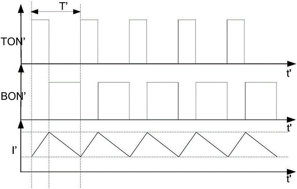
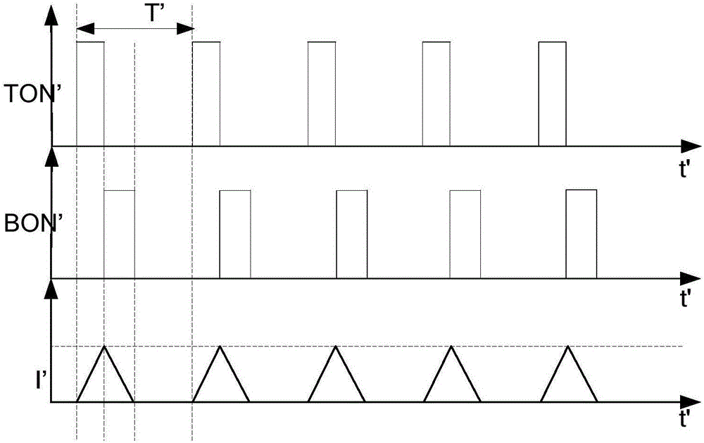
[0038] Specifically, as Figure 4 As shown, when the inductor current ripple is Δi, the waveform of the inductor current I before spreading the conduction signal of the first switch tube is B, and the period of the conduction signal of the first switch tube is T; The waveform of the inductor current I after the conduction signal of the switch tube is spread-spectrum is C, and the time period extended by the period of the conduction signal of the first switch tube is D. It should be noted that the induc...

Embodiment 2

[0055] An embodiment of the present invention provides a control method for a switch circuit, the control method is applied to a switch circuit in a discontinuous conduction mode, and the switch circuit includes a first switch tube and a second switch tube, such as Figure 11 As shown, the control method includes: S1. Acquiring the first time, the first time is the falling edge of the conduction signal of the second switch tube in the current working cycle and the conduction of the first switch tube in the adjacent next working cycle The time between the rising edges of the signal; S2, compare the size of the first fixed time with the first time; S3, when the first time is less than the first fixed time, adjust the period of the conduction signal of the first switching tube to the first Two fixed time; S4, when the first time is greater than the first fixed time, the sum of the second time and the first fixed time is adjusted to the second fixed time to realize spread spectrum,...


PUM


Abstract

The invention discloses a control method and a control circuit of a switching circuit, and a corresponding switching circuit apparatus, relates to the technical field of circuits, and used for guaranteeing that the switching circuit works in a DCM and starts to spread spectrum after the DCM is in a certain depth, and avoiding the condition that the switching circuit starts to spread spectrum in a CCM. The control circuit comprises an obtaining module used for obtaining a first time; a comparison module connected with the obtaining module and used for comparing a first fixed time and the first time; and an adjusting module connected with the comparison module. When the first time is smaller than the first fixed time, the adjusting module adjusts the period of conduction signals of a first switch tube to a second fixed time; and when the first time is greater than the first fixed time, the adjusting module adjusts the sum of a second time and the first fixed time to the second fixed time to realize frequency spreading. According to the control circuit of the switching circuit, the switching circuit is controlled to spread spectrum.

Description

technical field [0001] The invention relates to the field of circuit technology, in particular to a control method for a switch circuit, a control circuit and a switch circuit device. Background technique [0002] Currently, a switch circuit (for example, a BUCK circuit) is a circuit commonly used in circuit design, such as figure 1 As shown, the BUCK circuit usually includes a first switch tube 1', a second switch tube 2' and an inductor 3', wherein the first switch tube 1' can be a MOS tube (Metal Oxide Semiconductor Field Effect Transistor, metal-oxide- semiconductor field effect transistor), the second switch tube 2' can be a freewheeling diode or a synchronous rectifier tube, Vin' is the input signal of the BUCK circuit, Vout' is the output signal of the BUCK circuit, and TON' is the first switch The conduction signal of tube 1'. [0003] Specifically, when the load of the switching circuit is large, the switching circuit is in CCM (Continuous Conduction Mode, continu...

Claims


Application Information

Patent Timeline
Patent Type & Authority Applications(China)
IPC IPC(8): H02M3/156
CPCH02M3/156H02M1/0003H03K17/14H03K5/26H03K19/20H03K17/04
Inventor 黄必亮陈小鹏徐峰任远程周逊伟
Owner JOULWATT TECH ZHANGJIAGANG INC LTD
Why Eureka
Try Eureka