Device and method of adjusting modulator output optical signal power balance

A technology of output power and signal power, which is applied in the field of optical modules, can solve problems such as large differential loss, affecting the transmission quality of optical modules, and affecting the working status of the sending end.

Inactive Publication Date: 2017-01-11
ZTE CORP
View PDF4 Cites 1 Cited by
  • Summary
  • Abstract
  • Description
  • Claims
  • Application Information

AI Technical Summary

Problems solved by technology

[0004] When the two polarization state output channels X and Y of the modulator are balanced at ±0.5dB, the differential loss range between the X channel and the Y channel of the modulator is ±1.5dB, and there is currently no method to adjust the transmitt

Method used


Image

  • Device and method of adjusting modulator output optical signal power balance
  • Device and method of adjusting modulator output optical signal power balance
  • Device and method of adjusting modulator output optical signal power balance

Examples


no. 1 example

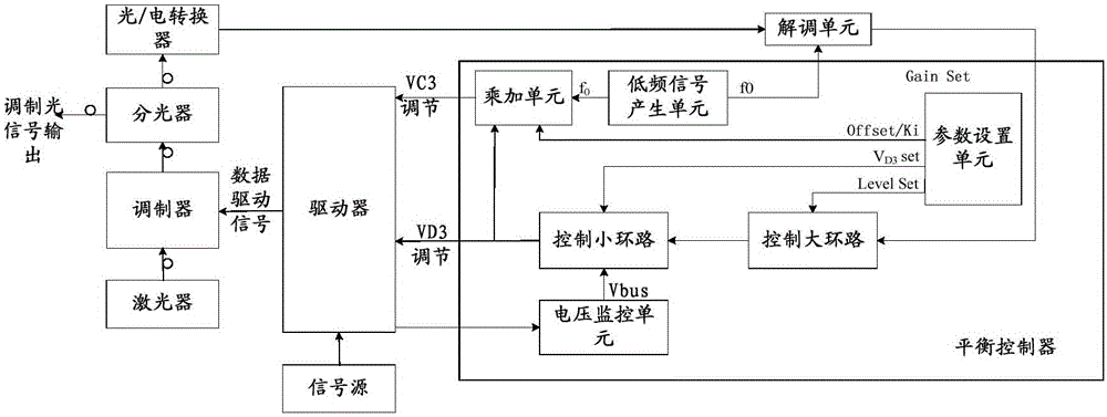
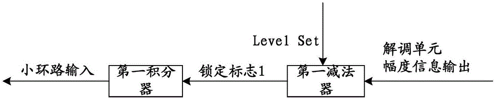
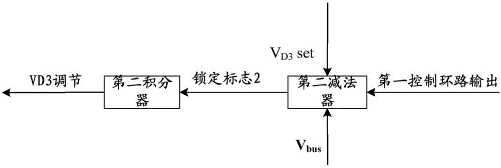
[0089] Such as figure 1 As shown, the first embodiment of the present invention provides a device for adjusting the power balance of the output optical signal of the modulator, the device includes a plurality of balance controllers, wherein the input of each balance controller passes through the demodulation unit, The amplifier and the optical splitter are connected to the output end of the modulator, the output end of each balance controller is connected to the driver, and each balance controller corresponds to one optical signal, and the balance controller includes: a parameter setting unit, a first control loop, The second control loop, the multiply-add unit, the low-frequency signal generating unit, and the voltage monitoring unit, wherein the first output end of the parameter setting unit is connected to the first input end of the first control loop, and the second output end of the parameter setting unit is connected to the first input end of the first control loop. The ...

no. 2 example

[0098] Such as Figure 4 As shown, the second embodiment of the present invention provides a method for adjusting the power balance of the output optical signal of the modulator, which is applied to the above-mentioned device for adjusting the power balance of the output optical signal of the modulator. The method includes:

[0099] Step S41, setting each balance controller according to the pre-obtained first value of the setting parameter of the first control loop of each balance controller and the second value of the setting parameter of the second control loop;

[0100] Step S42, receiving multiple optical signals sent by the modulator through the optical splitter, the demodulation unit and the transimpedance amplifier, wherein each balance controller corresponds to one optical signal;

[0101] Step S43, adjust the power of the received multiple optical signals through the multiple balance controllers with parameters set, so as to balance the power of the multiple optical s...

no. 3 example

[0104] Such as Figure 5 As shown, the third embodiment of the present invention provides a method for adjusting the power balance of the output optical signal of the modulator, which is applied to the above-mentioned device for adjusting the power balance of the output optical signal of the modulator. The method includes:

[0105] Step S51, obtaining the first value of the setting parameter of the first control loop and the second value of the setting parameter of the second control loop of each balance controller;

[0106] Step S52, setting each balance controller according to the pre-obtained first value of the setting parameter of the first control loop of each balance controller and the second value of the setting parameter of the second control loop;

[0107] Step S53, receiving multiple optical signals sent by the modulator through the optical splitter, the demodulation unit and the transimpedance amplifier, wherein each balance controller corresponds to one optical sig...


PUM


Abstract

The embodiment of the present invention provides a device and method of adjusting modulator output optical signal power balance, wherein the device comprises a plurality of balance controllers, the input end of each balance controller is connected with the output end of a modulator via a demodulation unit, a trans-impedance amplifier and an optical splitter, and the output end is connected with a driver. Each balance controller corresponding to an optical signal and comprises a parameter setting unit, a first control loop, a second control loop, a multiplication addition unit, a low-frequency signal generation unit and a voltage monitoring unit. According to the embodiment of the present invention, a driving amplitude 2V Pi can be detected adaptively, accurately and rapidly, and further when a differential phase shift keying eye pattern is locked via the found accurate 2V Pi, the power of the output optical signals can be adjusted automatically to guarantee the output optical signal power balance, thereby reducing the difference loss between the plurality of optical signals.

Description

technical field [0001] The invention relates to the technical field of optical modules, in particular to a device and method for adjusting the power balance of an output optical signal of a modulator. Background technique [0002] With the advent of the information age, society's demand for information has expanded rapidly, especially in the past decade or so, Internet traffic has been growing explosively. Optical fiber transmission network is the supporting foundation of the entire information network. As a new optical communication mode, high-speed optical transmission has become an international research hotspot to promote the development and technological progress of the next generation Internet and broadband mobile communication network. [0003] From the perspective of the development history of the optical fiber communication transmission system, every upgrade of the optical fiber transmission rate is accompanied by the innovation of the modulation format. 100Gbit / s ...

Claims


Application Information

Patent Timeline
IPC IPC(8): H04B10/564
CPCH04B10/564
Inventor 曹红凤
Owner ZTE CORP
Why Eureka
Try Eureka