Balance block and rotor assembly, shaft assembly and compressor with balance block

A technology of balance weight and rotor, which is applied in the field of compressors, can solve problems such as accelerated compressor wear and compressor vibration, and achieve the effect of increasing centripetal force

Inactive Publication Date: 2017-01-18
ZHUHAI GREE REFRIGERATION TECH CENT OF ENERGY SAVING & ENVIRONMENTAL PROTECTION
View PDF7 Cites 5 Cited by
  • Summary
  • Abstract
  • Description
  • Claims
  • Application Information

AI Technical Summary

Problems solved by technology

[0005] Therefore, the technical problem to be solved by the present invention is to overcome the large mass of the balance weight used to offset the eccentricity generated by the crankshaft in the prior art. When the rotating shaft rotates at a low speed, it is easy to cause vibration of the compressor and accelerate the wear

Method used


Image

  • Balance block and rotor assembly, shaft assembly and compressor with balance block
  • Balance block and rotor assembly, shaft assembly and compressor with balance block
  • Balance block and rotor assembly, shaft assembly and compressor with balance block

Examples


Embodiment 1

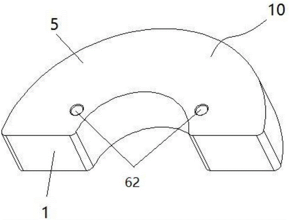
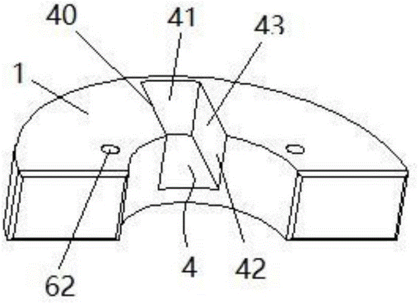
[0056] This embodiment provides a kind of balance weight, such as Figure 2-4 As shown, it includes: a main body 1, which is suitable for being installed on a rotatable part; a moving block 2, which is connected to the main body 1 through an elastic part 3; when the rotatable part rotates, the moving block 2 can press toward Or stretch the direction of movement of the elastic member 3, thereby changing the relative position of the moving block 2 and the main body 1, thereby changing the distance between the center of mass of the balance weight 10 and the rotation axis of the rotatable member .

[0057] In the balance weight of this embodiment, when the rotatable member rotates, the moving block 2 can move toward the direction of squeezing or stretching the elastic member 3, thereby changing the relative position between the moving block 2 and the main body 1, and then changing the center of mass of the balancing weight 10 The distance from the axis of rotation of the rotatabl...

Embodiment 2

[0067] itself provides a rotor assembly such as Figure 5-6 As shown, it includes a rotor 7 and a balance weight 10 fixedly installed at one end of the rotor 7, and the balance weight 10 is the balance weight described in Embodiment 1.

[0068] The rotor 7 includes a rotor main body 70 , and a front end cover 71 and a rear end cover 72 mounted on both axial ends of the rotor main body 70 , and the balance weight 10 is installed on the front end cover 71 or the rear end cover 72 .

[0069] The rotor assembly in this embodiment has all the advantages brought by the installation of the above-mentioned balance weight 10 due to the installation of the above-mentioned balance weight 10 .

Embodiment 3

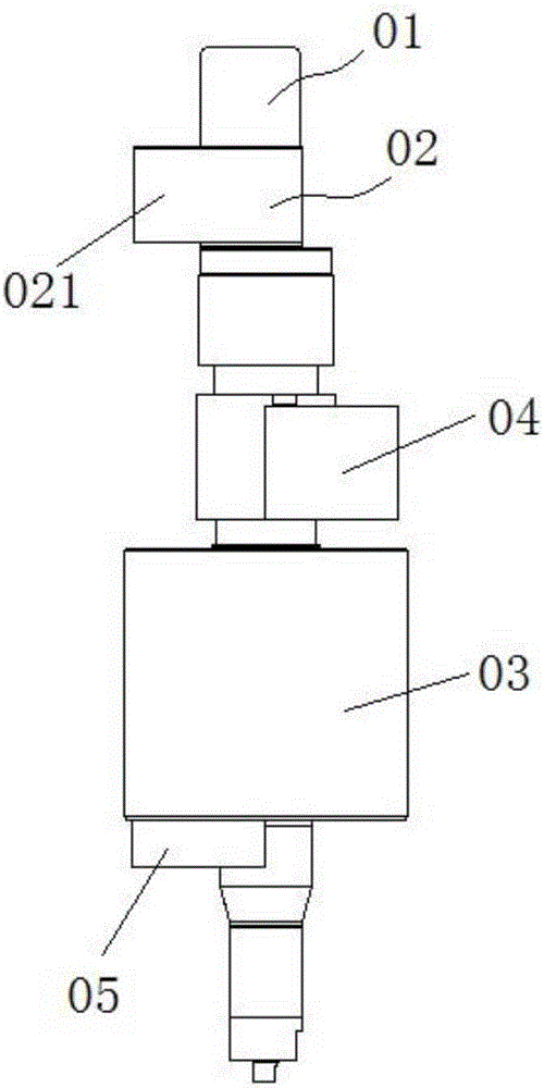
[0071] This implementation provides a shafting assembly such as Figure 7 As shown, it includes: a rotating shaft 81; a crankshaft 82, which is installed on the rotating shaft 81, and has a crankshaft eccentric portion 83; a rotor 7, which is installed on the rotating shaft 81; a main balance weight 84, which is fixedly installed on the rotating shaft 81 and / or Or on the rotor 7, and located on the opposite side of the eccentric portion 83 of the crankshaft; the auxiliary balance weight 85 is fixedly installed on the rotating shaft 81 and / or the rotor 7, and is located on the same side of the eccentric portion 83 of the crankshaft. side; the auxiliary balance weight 85 is the balance weight described in Embodiment 1.

[0072] In order to ensure the balance of the shaft system, the dynamic and static balance check of the compressor must satisfy the following formula:

[0073] m 1 ...


PUM


Abstract

The invention provides a balance block and a rotor assembly, a shaft assembly and a compressor with the balance block. The balance block comprises a main body (1) and a movable block body (2), wherein the main body (1) is suitable for being installed on a rotatable piece; and the movable block body (2) is connected with the main body (1) through an elastic piece (3). When the rotatable piece rotates, the movable block body (2) can move in the direction that the elastic piece (3) is squeezed or stretched, so that the relative positions of the movable block body (2) and the main body (1) are changed, and then the distance between the center of mass of the balance block (10) and a rotation shaft of the rotatable piece is changed. According to the balance block, under the condition that the mass of the balance block is small, the centripetal force is improved by increasing the distance between the center of mass of the balance block and the rotation shaft of the rotatable piece, and the beneficial technical effects that the eccentric magnitude generated when a crankshaft rotates can be counteracted, and the situation that vibration of the compressor is caused during low-speed rotation due to the large mass of the balance block, and consequently abrasion of the compressor is accelerated is avoided are achieved.

Description

technical field [0001] The invention relates to the technical field of compressors, in particular to a balance weight, a rotor assembly with the same, a shaft assembly and a compressor. Background technique [0002] A compressor in the prior art usually includes a cylinder body, a crankshaft, a rotor, a stator and other components. The crankshaft is fixedly connected to the rotor, and when the rotor rotates, it drives the crankshaft to rotate. The crankshaft has an eccentric part, and a compression chamber is formed between the eccentric part and the cylinder of the compressor. When the crankshaft rotates, the volume of the compression chamber between the eccentric part and the compressor cylinder changes periodically, thereby realizing the compression of the refrigerant. Because the eccentric part of the crankshaft will generate unbalanced inertia force during the rotation process, the compressor will vibrate during operation, and the vibration problem of the compressor is ...

Claims


Application Information

Patent Timeline
IPC IPC(8): F04C29/00
CPCF04C29/0021F04C29/0042F04C2240/60F04C2240/807
Inventor 朱晓光刘锋刘才
Owner ZHUHAI GREE REFRIGERATION TECH CENT OF ENERGY SAVING & ENVIRONMENTAL PROTECTION
Why Eureka
Try Eureka