Servo hydraulic device

A technology of hydraulic station and hydraulic oil tank, which is applied in the direction of fluid pressure actuation device, servo meter circuit, fluid pressure actuation system components, etc., and can solve the problems of high cost, small displacement range, complex structure, etc.

Inactive Publication Date: 2017-01-18
德玛仕电液技术(苏州)有限公司
View PDF6 Cites 0 Cited by
  • Summary
  • Abstract
  • Description
  • Claims
  • Application Information

AI Technical Summary

Problems solved by technology

[0004] Purpose of the invention: In order to overcome the problems of small displacement range, high cost, complex structure and small displacement range of existing hydraulic servo valves in the prior art, the present invention provides a servo hydraulic device

Method used


Image

  • Servo hydraulic device

Examples


Embodiment 1

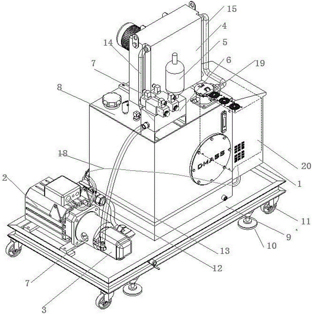
[0010] like figure 1 Shown is a servo oil pump device, a servo oil pump device, including a servo driver 1, a servo motor 2, a silent gear pump 3, an air cooler 4, a bladder accumulator 5, an integrated oil circuit board 6, a solenoid valve 7, Hydraulic oil tank 8, tray 9, fixed feet 10, universal wheels 11, low-pressure hose 12, high-pressure hose 13, first seamless steel pipe 14, second seamless steel pipe 15, solenoid valve 16, elastic coupling and bell Cover bracket 17, cable 18, oil return filter 19, the servo motor 2 is connected with the silent gear pump 3 through the elastic coupling 17, and the silent gear pump 3 is connected with the hydraulic oil tank 8 through the low-pressure hose 12, the The hydraulic oil tank 8 is connected to the electric control box 20, the electric control box 20 is provided with a servo driver 1, the servo driver 1 is connected to the servo motor 2 through a cable 18, and the silent gear pump 3 is connected to the integrated oil pump through...

Embodiment 2

[0017] like figure 1 Shown is a servo oil pump device, a servo oil pump device, including a servo driver 1, a servo motor 2, a silent gear pump 3, an air cooler 4, a bladder accumulator 5, an integrated oil circuit board 6, a solenoid valve 7, Hydraulic oil tank 8, tray 9, fixed feet 10, universal wheels 11, low-pressure hose 12, high-pressure hose 13, first seamless steel pipe 14, second seamless steel pipe 15, elastic coupling and bell bracket 17, Cable 18, oil return filter 19, the servo motor 2 is connected to the silent gear pump 3 through the elastic coupling 17, the silent gear pump 3 is connected to the hydraulic oil tank 8 through the low-pressure hose 12, and the hydraulic oil tank 8 is connected to the The electric control box 20 is connected, and the electric control box 20 is provided with a servo driver 1, and the servo driver 1 is connected to the servo motor 2 through a cable 18, and the silent gear pump 3 is connected to the integrated oil circuit board 6 thro...


PUM


Abstract

The invention discloses a servo hydraulic device. A tray is provided with a servo driver, a servo motor pump combination and a hydraulic oil tank. The servo driver is connected with a servo motor through a connecting cable. The servo motor is connected with a mute gear pump through an elastic coupling and is fixed through a bell jar bracket. The oil tank is connected with the mute gear pump through a low-pressure hose. The mute gear pump is connected with an integrated oil line plate through a high-pressure hose. The integrated oil line plate is installed on the hydraulic oil tank. A bladder-type energy storage device is installed on the integrated oil line plate. The integrated oil line plate is connected with an air cooler through a first seamless steel pipe. The air cooler is connected with a return oil filter installed on the oil tank through a second seamless steel pipe. The oil tank and the tray are fixed through ground feet. The bottom of the tray is provided with fixed feet and universal wheels. The servo hydraulic device is low in cost and wide in delivery capacity range and achieves the effects of simplifying the structure of a hydraulic system, saving energy and reducing emissions.

Description

technical field [0001] The invention relates to a servo hydraulic device, in particular to a servo hydraulic device, which belongs to the technical field of factory equipment. Background technique [0002] In response to my country's energy-saving and emission-reduction requirements, industrial hydraulics are also transforming towards energy conservation. The electro-hydraulic servo system, because of its good energy-saving effect, has been more and more valued and used by plastic machinery, die-casting machinery, shoe leather machinery, textile machinery, hydraulic machines and other machinery industries. Servo oil pumps (electro-hydraulic servo pumps) can be used in Starting at low speed, it can adapt to the working conditions of fast and slow speed, high and low pressure, and fast switching of the electro-hydraulic servo system. The emergence of the electro-hydraulic servo pump has changed the situation that my country's servo hydraulic system has long relied on Japanese a...

Claims


Application Information

Patent Timeline
IPC IPC(8): F15B21/00F15B21/04F15B1/02
CPCF15B21/00F15B1/02F15B21/042F15B2211/20515
Inventor 耿马雨
Owner 德玛仕电液技术(苏州)有限公司
Why Eureka
Try Eureka